WaveFarer's surface and edge integration calculation relies on methods that utilize surface meshes. These meshes are composed of triangular facets, so it is imperative that the integral surfaces and edges be properly aligned.
This electromagnetic calculation is based on Physical Optics (PO) and supplemented with corrections to account for edge effects using the Method of Equivalent Currents (MEC). The nature of these methods requires well-defined geometry in order to yield accurate simulation results. Flaws in CAD models, including gaps, hanging edges, missing faces, and overlapping or intersecting facets, can cause the calculation methods to incorrectly interpret the surface of the geometry and negatively impact results.
General Guidelines
Well-formed CAD models meet the following criteria:
- A mesh defines one or more closed surfaces without holes, gaps, or overlaps.
- Two joined facets align at both common vertices and common edges.
- Each facet has one adjoining facet on each of its sides. In cases such as a knife edge, the reverse side is considered the adjoining facet.
- An edge shared by two facets is considered one edge, and a shared vertex is considered one vertex. Edges that are not shared do not overlap or cross.
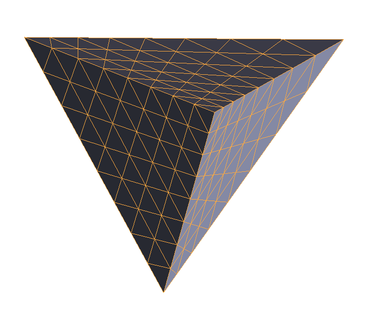
- Meshes that meet the first four criteria should have the lowest possible aspect ratios in order to maximize simulation accuracy and reduce run time. Facets with a non-zero area are valid, but may not be optimal.
Well-Constructed CAD Models
The following examples adhere to the general guidelines.Sphere
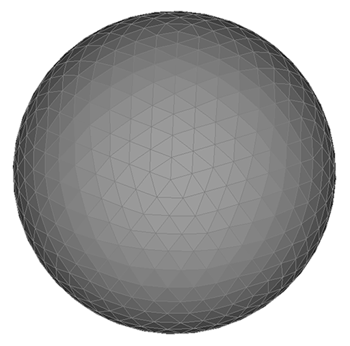
This simple geometric model demonstrates proper edge and vertex alignment of the mesh, and displays facets with low aspect ratios. Long, narrow triangles are less efficient than equilaterial or near-equilaterial triangles.
Generic Aircraft
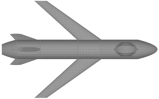
This generic aircraft follows the first four guidelines. Though some of the facets are narrow, it is considered a structurally sound CAD model for simulation purposes.

The joint of the wing root to the aircraft's body demonstrates proper mesh alignment with regard to the shared edges and vertices between facets. The facets are outlined in red for increased visibility.
Problematic CAD Facets
The following examples use simple geometry to demonstrate some common facetization errors in 3-D CAD modeling.Overlapping Facets
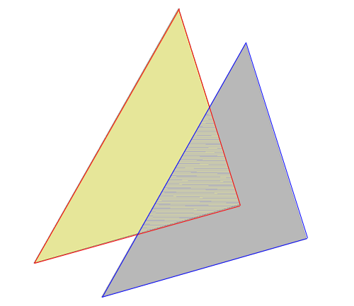
These two coplanar facets have vertices that do not match, resulting in a portion of each facet occupying the same space. The yellow and blue facets show how the overlapping area of conflict is rendered.
Intersecting Facets
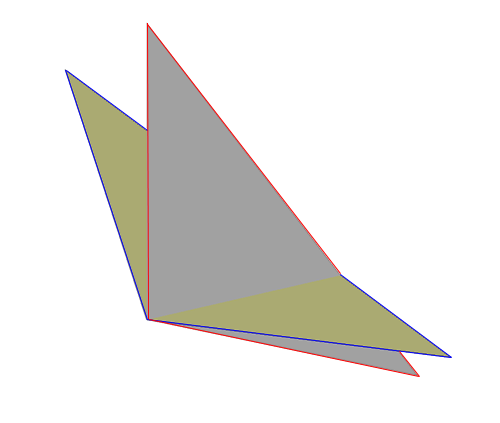
These two facets have vertices that cause them to pass through one another. The resulting point of intersection does not have either a defined edge or vertices, and will be processed incorrectly during a simulation.
Adjacent Facets Without Edge and Vertex Alignment
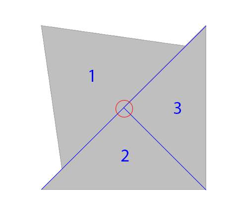
In the facets pictured, 2 and 3 share both an edge and vertices. The shared vertices circled in red is located on an edge of facet 1, meaning that the vertices of facet 1 are not shared with its neighboring facets. The mesh of this geometry is not aligned, and therefore not valid.