The  Check Model feature validates the backend definition of a part and returns any errors that are found. This serves as a diagnostic tool for users who suspect a problem with their geometry and have no other troubleshooting options.
This feature is helpful when identifying issues resulting in the following situations:
- A modeling operation fails.
- The mesh is problematic.
Workflow
XF maintains two expressions of three-dimensional CAD models—the solid model and the rendered model. The solid model is not visible to users because it is the geometry's backend mathematical representation, such as a sphere with a radius of 1 mm. XF's rendering algorithm transforms the solid model into the rendered model that appears in the drawing area. Inconsistencies in the backend's solid model may not be visible in the rendered model.
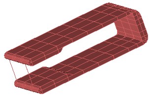
A problem with the solid model presents itself in one of two ways, each of which is visible to users. In the first situation, a failed modeling operation—such as a boolean, shell, or bend—results in a part that disappears from the Geometry window, and has a  next to it in the Project Tree. Resting the cursor on the symbol produces a brief message that may help users understand why the operation failed. In the second situation, non-physical lines appear in the Mesh view, indicating a problem that is not obvious in the rendered model. Users can troubleshoot either of these scenarios by performing a check.
The Check Model feature locates problems and produces a list of errors associated with the solid model. These errors are often cryptic because they reflect the backend's solid model parameters. The presence of a list, rather than the error messages within it, is what guides users toward the appropriate next step.
An empty list indicates that no issues were identified with the model and that the problem lies elsewhere. When errors are present, users can determine the best course of action based on the information provided. The options include the feature's Attempt to Fix capability, XF's Heal function, reimporting an updated version of the CAD model, and contacting customer support for assistance. Users may also fix the errors directly if they can interpret the error messages.
Controls
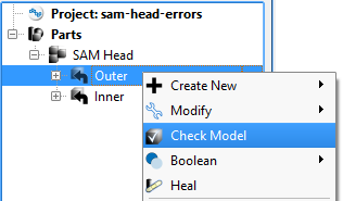
Identify problems with your 3-D CAD model using the check model feature by right-clicking on the part in the Project Tree and selecting Check Model.
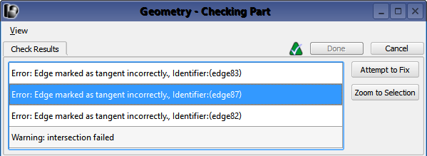
Results are listed across the top of the Geometry window. Once a result is selected, click Zoom to Selection for a closer view of the geometry containing the selected error.
The Attempt to Fix option detects minor data flaws associated with the selected error and tries to repair them.
For issues that do not respond to the Attempt to Fix option and require more involved changes to the geometry, users should heal the part by right-clicking on it in the Project Tree and selecting Heal.
If the errors persist after utilizing both options, users should import an updated version of the CAD model or contact Remcom's customer support for assistance.