A standard for distinguishing two overlapping parts ensures they are correctly applied to the mesh, and avoids sending a questionable mesh to the calculation engine for simulation.
Background
Each cell edge in the finite-difference time-domain (FDTD) grid requires that a single material be assigned to it. When parts with different materials overlap, it becomes difficult to determine which of those materials should be applied to the mesh. The meshing order is XF's mechanism for removing ambiguity. Parts are applied to the mesh sequentially according to the meshing order, so that each subsequent part supplements the filled in mesh.
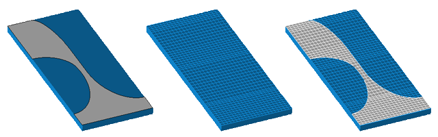
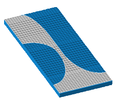
The left figure in the following example shows a CAD model of an antenna printed on a substrate. The mesh in the middle figure represents the substrate with a meshing order of one and the conductor with a meshing order of two. This is problematic because the conductor was not included in the mesh and will therefore not be included in the simulation. The mesh in the figure on the right shows the issue is corrected when the conductor's meshing order is one and the substrate's meshing order is two.