XF's  Touching Objects functionality tests and separates intersecting objects in the mesh. This ensures correct electrical disconnectivity in the mesh between two parts separated by a minimal distance in the CAD space.
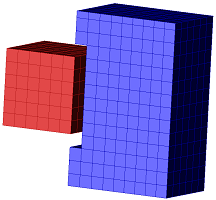
The finite-difference time-domain (FDTD) simulation space is discretized into cells, called the grid, and the mesh specifies which material properties are associated with each cell edge. The process of meshing, or transferring CAD representations into this discretized space, occassionally produces unintended effects. One such situation involves two geometric objects positioned close together without touching in CAD space, but that intersect in the mesh. Unless corrected, this can lead to inaccurate results due to a short-circuiting effect in the calculation.
There are three methods for addressing intersecting parts. The first option is moving the objects further apart, which is not a viable solution for every geometric design. The second option is creating a grid region with cells small enough to resolve the separation between objects. However, this decreases the cell size and increases the timestep, which increases the computation resources required to run the simulation.
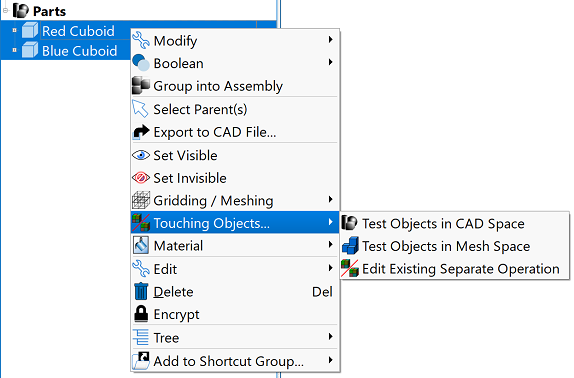
XF's third option identifies and corrects unwanted effects caused by meshing and geometric positioning with tools that test and separate objects. Users can access the Touching Objects functionality by selecting the two parts of interest in the Project Tree, then right clicking and selecting Touching Objects to choose from the available options.
Test Objects
The Touching Objects right-click menu offers two test options:
- Test Objects in CAD Space: determines whether the parts touch each other in CAD space.
- Test Objects in Mesh: determines whether the parts touch each other in the mesh.
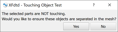
Both options open the Touching Object Test editor, which asks whether or not to separate the objects in the mesh.
The editor contains two buttons:
- Yes: closes the current editor and opens the Separate Objects in Mesh editor.
- No: closes the current editor.
Separate Objects in Mesh
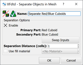
Choosing Separate Objects in Mesh from the Touching Objects right-click menu opens the Separate Objects in Mesh editor. This editor also opens by clicking the Yes button in the Touching Object Test editor. The Name field at the top identifies the operation for future reference, and the Separation Options section provides settings that apply to the named parts.
The selected Enable option activates the settings by default and disables them when deselected. The uneditable Primary Model and Secondary Model correspond to the two parts selected in the Project Tree, and can be reversed by clicking the Swap Inputs button.
The Separation Distance (cells) setting defines the number of cells to insert between the objects.
Checking the Use fill material option activates the drop-down menu listing the project's available materials. The selected material is assigned to the cells filling the distance between the separated objects.
- OK: saves the entered specifications and closes the editor.
- Cancel: discards the entered specifications and closes the editor.
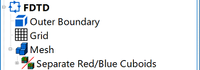
Users can view the list of touching object mesh operations applied to a project by expanding the Mesh node in the Project Tree.