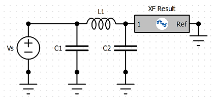
The schematic editor allows users to create circuits by placing, connecting, and editing individual elements, and then run a circuit simulation. Users can also save circuit results and apply them to FDTD simulation results during post-processing.
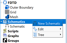
Users can create a schematic by right-clicking on Schematics in the Project Tree and selecting New Schematic. An existing circuit's editor is accessed by double-clicking on the desired schematic in the Project Tree or by right-clicking on the desired schematic and choosing Properties.
Menu & Toolbar
There are four menus available in the upper-left corner of the editor: file, edit, view, and tools. Users can perform many of the same actions available through these menus by clicking the corresponding button in the toolbar. The Name field provides space for a user-defined schematic identifier.

The following tools and buttons are available:
 : commits unsaved changes to the project.
 : discards changes and restores the circuit to the previous saved version.
 : runs the circuit simulation.
  : accesses the analysis workbench editor with tuning capability.
 : runs the optimizer for the schematic.
 : accesses the operating mode editor.
 : sets the range of allowable component values used during optimization.
 : defines the schematic's optimization goals.
 : accesses the substrate editor.
 : undoes the last action.
 : redoes the last undone action.
 : deletes the selected element in the schematic window.
 : centers the entire circuit within view.
 : enlarges the schematic while keeping all circuit elements within view.
  : returns to the default zoom setting.
 : zooms in on the schematic view.
 : zooms out on the schematic view.
 : enables the zoom tool, which zooms in on a selected portion of the schematic window.
 : enables the on-screen display.
 : enters and leaves a subcircuit.
 : accesses summary of schematic's achieved goals.
 : enables the wire tool.
 : enables the ground tool.
 : enables the auto-connector tool, which provides an alternative to wires for connecting component terminals.
 : enables the multi-tool.
 : enables the deactivate tool, which deactivates the selected element.
 : enables the vertical mirror tool, which flips the selected element along the x-axis.
 : enables the horizontal mirror tool, which flips the selected element along the y-axis.
 : enables the rotate tool, which rotates the selected element 90 degrees in the clockwise direction.
Additionally, the Tools menu offers access to the same basic components and simple transmission lines provided in the workspace tab in the lower portion of the editor.
Workspace Tab
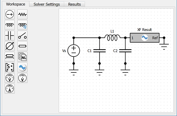
The Workspace tab includes a functional schematic display that allows users to add, move, and edit individual circuit and transmission line components. Users can click on a component or transmission line placement tool on the left side of the tab, and then place it in a desired location in the schematic window on the right.
Solver Settings Tab
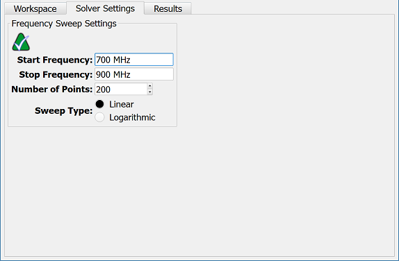
The Solver Settings tab defines input values for computing a circuit's results. The  button accesses the default Direct Solver and the alternative Iterative Solver options.
The Frequency Sweep Settings include editable fields that set the frequency range and sampling for the frequency-domain circuit solver:
- Start Frequency: the simulation's lower frequency.
- Stop Frequency: the simulation's upper frequency.
- Number of Points: specifies how many times the data is sampled over the frequency range defined by the upper and lower values.
The Sweep Type determines how a calculation sweeps through a frequency range and includes two available options:
- Linear: each frequency point is an equal step over the range.
- Logarithmic: the frequency points increase logarithmically over the range.
The Optimization Analysis Settings include two options for specifying which parameter controls the optimizer. Choosing the desired setting enables its associated editable field.
- Number of Particles: the number of possible solutions included in the population.
- Particles Per Variable: the number of possible solutions for a given variable.
The Max Iterations value determines the greatest number of computations allowed during optimization.
The Advanced options are specific to the particle swarm. Users can enter the desired values, as well as utilize the two checkbox options at the bottom of the window. Mousing over these options displays a tooltip with additional information.
- Neighborhood Size: the extent of social interaction within the swarm. The smaller the swarm's neighborhoods, the fewer the interactions between them.
- Number of Predators: the amount of variablity pushing a prey's swarm out of a local minimum.
CVT, or Pseudo Centroidal Voronoi Tessellation, is an initialization method that attempts to evenly distribute the starting population within the search space. When checked, the CVT option can reduce the variance of results and increase the effectiveness of the search at the cost of longer initialization times.
Human Behavior is a particle behavior strategy that, when checked, includes negative feedback from the population's worst performers, as well as the standard behavior of the population's best performers.
Results Tab
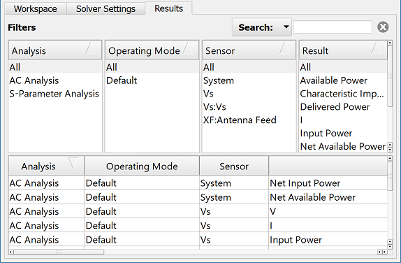
The Results tab displays schematic results once the circuit simulation is complete. The four panes in the upper portion of the browser filter the results, and the lower portion contains a list of all the results that meet the criterion set by the selections in the upper columns.
By default, the result filters are set to Analysis, Operating Mode, Sensor, and Result, but users can configure the order in which they appear in the four upper panes by right-clicking on a header and making the desired selection.
Double-clicking on a result generates that data's default graph, and right-clicking, then choosing Create Line Graph accesses non-default views.
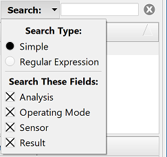
In the upper-right corner of the window, users can manually enter text into the Search field and use the drop-down arrow to access additional filtering criteria.
The Search Type determines what search terminology is considered valid:
- Simple: default search for case insensitive text matches, which are displayed as terms are entered.
- Regular Expression: case insensitive search for multiple terms separated by a vertical bar without spaces, and followed by pressing Enter. For example, band 1|system.
When choosing the Regular Expression search, users should note that entering a space either before or after a vertical bar returns incomplete search results. The Search These Fields options specify which fields are searched for the terms entered in the Search bar. The available selections include fields with either numeral or text entries, such as Analysis, Operating Mode, Sensor, and Result.

 : commits unsaved changes to the project.
 : discards changes and restores the circuit to the previous saved version.
 : runs the circuit simulation.
  : accesses the analysis workbench editor with tuning capability.
 : runs the optimizer for the schematic.
 : accesses the operating mode editor.
 : sets the range of allowable component values used during optimization.
 : defines the schematic's optimization goals.
 : accesses the substrate editor.
 : undoes the last action.
 : redoes the last undone action.
 : deletes the selected element in the schematic window.
 : centers the entire circuit within view.
 : enlarges the schematic while keeping all circuit elements within view.
  : returns to the default zoom setting.
 : zooms in on the schematic view.
 : zooms out on the schematic view.
 : enables the zoom tool, which zooms in on a selected portion of the schematic window.
 : enables the on-screen display.
 : enters and leaves a subcircuit.
 : accesses summary of schematic's achieved goals.
 : enables the wire tool.
 : enables the ground tool.
 : enables the auto-connector tool, which provides an alternative to wires for connecting component terminals.
 : enables the multi-tool.
 : enables the deactivate tool, which deactivates the selected element.
 : enables the vertical mirror tool, which flips the selected element along the x-axis.
 : enables the horizontal mirror tool, which flips the selected element along the y-axis.
 : enables the rotate tool, which rotates the selected element 90 degrees in the clockwise direction.