
Operating modes facilitate the simulation of both multi-state and variable components within a single schematic design. Examples of these components include the following:
- Impedance and aperture tuning of antennas.
- Digital phase shifters in phased array designs.
- Full-wave FDTD blocks accounting for multiple environments, such as antenna placement on a platform or user equipment with human body phantoms.
Each operating mode defines the states of variable components, leaving the fixed components static for the design as a whole. Results are produced for each operating mode for analysis of the component's performance in each state. By defining the component properties for each band, beam, or environment, a single schematic provides comprehensive results in a single simulation.
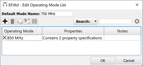
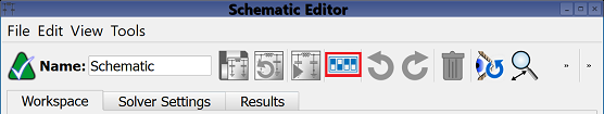
Users can access this functionality by clicking the Edit Operating Modes button in the toolbar at the top of the Schematic Editor to open the Edit Operating Mode List window.
Operating Mode List

The Edit Operating Mode List allows users to maintain a schematic's available modes, which are added and removed using the buttons above the list:
: adds an operating mode.
: deletes the selected operating mode.
: copies the selected operating mode.
: pastes the copied operating mode.
: provides a flat table view of operating mode information.
The list provides basic information about each defined operating mode, including its name, number of specified properties, and any attached memos in the Operating Mode, Properties, and Notes columns, respectively.
An operating mode is enabled or disabled by either selecting or deselecting its associated checkbox. A disabled operating mode is ignored by the frequency-domain circuit solver and its results are therefore unavailable. Users can edit an existing operating mode by double-clicking in its associated Properties column.
Two buttons are available at the bottom of the Edit Operating Mode List and each of its nested editors:
- OK: closes the active editor and saves the entered specifications.
- Cancel: closes the active editor and does not save the entered specifications.
Saving changes to a new or existing operating mode clears results previously computed by the frequency-domain circuit solver.
Defining an Operating Mode

Clicking the button in the Edit Operating Mode List window opens the Edit Operating Mode editor that allows users to define its component properties. Users can also open this editor to adjust an existing operating mode's properties by double-clicking on the desired operating mode in the Edit Operating Mode List window. The Name field provides space for a user-defined component identifier, and the selected Enabled option activates the component by default.
The Component Properties tab allows users to add, remove, and define component properties using the buttons above the list:
: adds a component property to the list and opens the Specify Property editor.
: deletes the selected component property.
- Import: imports a property configuration from a previously exported XML file with the option to replace, merge, or append the incoming list.
- Export: exports the selected properties in the configuration to an XML file.

The Specify Property editor defines a component's properties with options in two drop-down menus. The upper drop-down menu lists each element in the current schematic, and the lower drop-down menu lists all available properties associated with the selected element.
Once a component property is added to the table, users can edit its value by double-clicking on the desired cell. The value specification is tailored to the property type.
The Notes tab provides space for users to attach memos to the operating mode, such as a brief description of its specifications for later reference.
Detailed Information List

Clicking the button in the Edit Operating Mode List window opens the Schematic Operating Modes Detailed Info list, allowing users to view a read-only list of component property values for each operating mode. The Operating Mode column lists the name of each operating mode, with a value for each of its specified properties appearing in a separate column to the right. The Default operating mode represents the component values as they are defined in the schematic's workspace tab.
Two settings determine which details are displayed. Checking the All Properties option expands the list to include a column for every component property included in the schematic. When deselected, only properties that change state in one or more operating modes are shown. Checking the Default Values option fills in every cell in the table. Unchecking this option fills cells only if they differ from the default operating mode.
Clicking the button exports the table to a comma-separated value (CSV) file for reference and post processing. The exported data fills the default values, regardless of the check box state, in order to avoid empty data in the CSV.
Clicking Done closes the Schematic Operating Modes Detailed Info window and saves any selected options, which are visible when the window is re-opened.