
Circuit Element Optimization
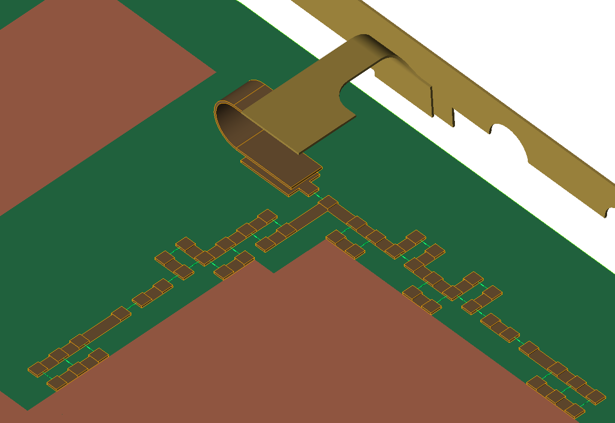 Initially designed for matching circuit optimization, the circuit element optimizer (CEO) determines optimal component values while considering a multitude of EM effects on the real circuit's physical layout.
Using XF's full-wave finite-difference time-domain (FDTD) solver, the CEO is able to account for the following EM effects:
- Parasitic and couple effects within the matching network layout.
- Coupling between the matching network and antenna being tuned.
- Coupling between antenna being tuned and other antennas.
- Physical configurations, such as free space, held in hand, and held near head.
- Fixed resistors, capacitors, and inductors.
- Ideal resistors, capacitors, and inductors.
- Realistic capacitors and inductors with user defined equivalent series resistance.
- Passive tunable integrated circuits, or tuners.
Electrostatic Solver with Capacitance Matrices
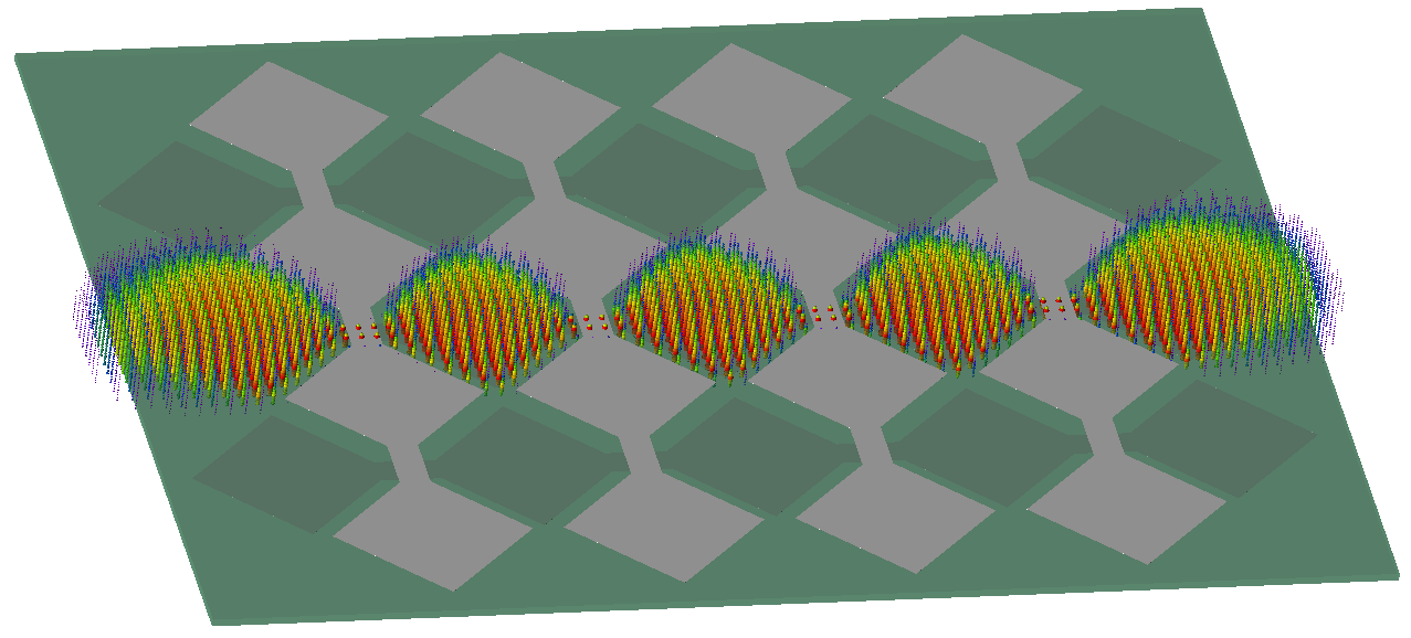 The Electrostatic Solver has been enhanced to increase its accuracy and expand its potential applications.
Improvements within the calculation engine include the following capabilities:
- Consider dielectric materials while computing fields.
- Compute charge. Charge is used in capacitance calculations so self- and mutual- capacitance are available in the Spice and Maxwell formulations.
- Handle variable cell sizes in the grid.
- Apply a voltage to individual parts or an assembly. A single part with multiple, unconnected bodies can have the same potential.
- View volumetric results for voltage or electric field.
Time Dependent Material
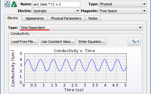 This new material type allows XF users to specify a material's permittivity and conductivity as a function of time. The inputs can be specified as a constant value, loaded from a file, or entered as an equation. As the timestepping stage of a simulation proceeds through time, the material properties are modified accordingly.
Softkill Termination for Timestepping
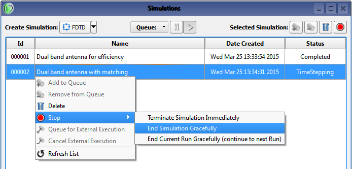
An FDTD simulation proceeds through the following stages: initialization, timestepping, steady-state post-processing, and writing output. The softkill feature allows users to terminate the timestepping stage of a simulation and proceed to steady-state post-processing.
Through the UI, users can terminate timestepping by right-clicking on the simulation in the Simulations window and choosing Stop. Alternatively, create a file named project.softkill in the *.xf/Simulations/### directory to kill a simulation, or create the file in .../Simulations/###/Run### to kill the run, but continue the simulation.
Additional Capabilities
This version introduced over 40 usability, performance, scripting, and other updates.Here is a select list of modifications:
- Changed the modulation interference factor in the HAC sensor settings from linear scalar units to dB.
- Added create project archive option to the file menu, enabling users to package a project for either archiving or sending to Remcom Technical Support.
- Clarified the import and export buttons in the ODB++ import dialog.
- Changed the default view for steady-state far zone results to vector magnitude with RMS, and included vector magnitude with phase as an option available for selection.
- Removed vector magnitude and complex phase results reported in the results browser, typically via the ResultQuery scripting API.
- Dispersive electric materials, including Debye-Drude and Lorentz, can neighbor or overlap parts that are meshed with XACT. However, parts with dispersive material assignments cannot mesh with XACT themselves.
- Added a thumbnail image of the geometry view to the dialog window when saving a project. The thumbnail is also visible when loading that project.
- Added enable and disable functionality to static voltage definitions.
- Added ability to assign static voltage per part in addition to by point. This allows multi-lump parts to be treated as if they are connected.
- Added ability to combine data into a single trace when combining results in the create line graph dialog.
- [Scripting API] Added ResultQuery.getStatus()
- [Scripting API] Added Selectable.getDisplayName()
- [Scripting API] Added MathUtils.formatNumber() functions to convert numbers to strings, formatting them nicely.
- [Scripting API] Added SimpleScrollArea to provide scrollbars for dialogs with many widgets.