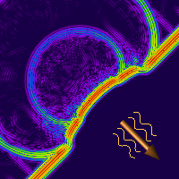
 Plane Wave source is assumed to be infinitely far away so that the constant field surfaces are planar and normal to the direction of propagation. The excitation is useful for computing scattering behavior and radar cross section.
Create and Edit
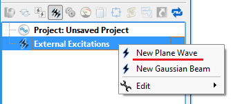 Access the plane wave editor by right-clicking on the External Excitations branch of the Project Tree and choosing New Plane Wave, or double-clicking on an existing plane wave within the Project Tree. This opens an editor at the top of the Geometry window that consists of a Location tab and a Properties tab.
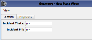
Under the Location tab, specify the incident direction of the Plane Wave by entering values for both Incident Theta and Incident Phi. These angles are defined in XF's spherical coordinate system where theta, $\theta$, is referenced from the z-axis and phi, $\phi$, is referenced from the x-axis. Verify the incident direction by viewing the yellow indicator arrow in the Geometry window.
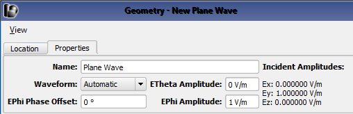
Under the Properties tab, identify the excitation by filling in the Name and select the Waveform. The ETheta Amplitude $E_\theta$, EPhi Amplitude $E_\phi$, and EPhi Phase Offset $\psi$ fields define linearly, circularly, or elliptically polarized plane waves.
- Linear: $E_\theta \neq 0$ and/or $E_\phi \neq 0$ and $\psi = 0^\circ$
- Circular: $E_\theta = E_\phi$ and $\psi = \pm 90^\circ$
- Elliptical: $E_\theta \neq 0$, $E_\phi\neq 0$, $\psi \neq 0^\circ$, and circular polarization criteria are not met.
Users should note that a sinusoidal waveform is required when defining a circular or elliptical polarization.
Consider a time-harmonic plane wave traveling in the negative Z direction, $(\theta,\phi) = (0,0)$ and the following example polarizations, which can be defined through the editor.
| Polarization | $E(x,y,z)$ | ETheta Amplitude | EPhi Amplitude | EPhi Phase Offset |
|---|---|---|---|---|
| Linear | $E_xe^{j\omega z}$ | 1 | 0 | 0 |
| Linear | $(E_x + E_y)e^{j\omega z}$ | 1 | 1 | 0 |
| Circular | $(E_x + jE_y)e^{j\omega z}$ | 1 | 1 | $90^\circ$ |
| Elliptical | $(E_x + E_ye^{j\psi})e^{j\omega z}$ | 1 | 1 | $\psi$ |
Simulate
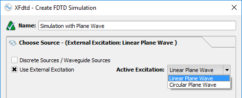 When multiple plane waves are created in a project, only one can be excited during a simulation. In the Create FDTD Simulation window, specify the Active Excitation under the Choose Source tab and utilize additional settings under the Specify Field Formulation tab.
Users should note that all active Circuit Components and Waveguide Interfaces will be set to passive loads and matched terminations, respectively, when a Plane Wave excitation is selected.