The  Outer Boundary refers to the outermost cell edges of the FDTD simulation space. The outer boundary conditions are a means by which the fields propagating toward the grid's outer edge are either absorbed or reflected. Two numerical absorbers allow electromagnetic fields that are either radiated or scattered by the geometry to be absorbed by the boundary with minimal reflection: perfectly matched layer (PML) and Liao. In cases where a reflecting boundary is preferred, the options include a perfect electric conductor (PEC) or a perfect magnetic conductor (PMC). XF also offers periodic boundary conditions that allow a one unit cell of an infinitely periodic structures to be modeled.
Background
The FDTD algorithm utilizes the Yee cell, where each electric field is surrounded by four magnetic cells. This allows Maxwell's curl equations to be solved during a simulation.
Because the simulation space is a finite size, electric cell edges on the outer boundary of the FDTD simulation space are not surrounded by four magnetic fields. Therefore, these cells cannot be updated with the Yee cell update equations.
Different methods exist for determining the field values at each timestep. A PEC boundary condition is the simplest method, where the field values are set equal to zero. The absorbing PML boundary condition artificially extends the simulation space with increasingly lossy layers.
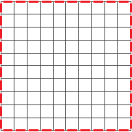
The FDTD simulation space is rectangular, separating the outer boundary into six sides: upper and lower x, y, z. Users can specify how the fields on the boundaries are calculated.
The PML boundary is comprised of an artificial material that absorbs the incident energy as it propagates through the PML layers. The artificial material's properties are matched to both the material normal and tangent to the boundary. Although the name implies a perfectly matched boundary, there are reflections from PML that decrease as the number of layers increase. This boundary condition provides better absorption then the alternative Liao method, and is recommended for use when possible. XF's default PML boundary setting with seven layers is based on its effective balance between accuracy and run time.
The Liao boundary estimates the electric fields on the boundary by applying a 1-D wave equation to the five fields immediately inside the simulation space. This method assumes a homogeneous material within five cells and risks an unstable calculation when this is not accurate. In order to ensure stability, using this method with a minimum space of ten cells between the radiating geometry and the outer boundary is recommended. Because the Liao boundary is not intended for graphic processing units (GPUs), XF reverts to the default PML boundary for simulations is run on a GPU.
The PEC boundary condition generates a reflection coefficient with 180 degree phase shift with the same magnitude.
The PMC boundary condition generates a reflection coefficient with a 0 degree phase shift with the same magnitude.
The Periodic boundary simulates a one-unit cell of an infinitely periodic structure. A periodic boundary cannot be combined with another boundary type for the same axis, so the upper and lower boundaries for a single axis must both be set to periodic.
Controls
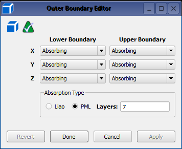
The outer boundary is defined in the Outer Boundary Editor, which is accessed by double-clicking on Outer Boundary in the FDTD branch of the Project Tree. The editor provides both a Lower Boundary and Upper Boundary setting for each of the three axes for a total of six sides. The lower and upper boundaries of each axis must be compatible with each other, but each axis is independent of other axes' selections. Each boundary's drop-down menu includes Absorbing, PEC, PMC, and Periodic.
There are two Absorption Type options: Liao and PML. The default PML option with seven layers can either be adjusted to the desired number of layers or changed to Liao. Because these two boundary types cannot be combined in the same calculation, selecting the Liao option immediately deactivates the layers field. The Absorption Type setting is applied to each Absorbing boundary selection in the upper portion of the editor.
The reflective boundaries are compatible with each other, as well as with an absorbing boundary. For example, either PEC or PMC can be selected for one or both boundaries of the same axis. Either of these reflective boundaries can also be combined with an Absorbing boundary of the same axis.
A Periodic boundary is not compatible with another boundary type, so choosing either a lower or upper periodic boundary immediately changes the other boundary of that axis to periodic.
Application-Specific Considerations
Some outer boundary configurations are commonly used:
- A radiating structure is absorbing on all sides in order to mimic a device in free space.
- An infinite PEC ground plane utilizes a PEC ground plane and five absorbing boundaries on the remaining sides.
- Frequency selective surfaces utilize periodic boundaries on the four sides intersecting the surface with absorbing boundaries on the sides above and below.