The  Slice modeling operation cuts one part into two parts. It is similar to a boolean chop, except that it utilizes a single cutting plane for a streamlined workflow. The slice operation can be used to separate an undesired portion of a part for deletion, such as the feeding structure of an antenna needing to be redesigned. Users specify the location and orientation of the cutting plane by either typing in the values or using the direction picking tools to make selections in the geometry window.
Users can slice multiple parts simultaneously by clicking in the Project Tree while pressing either Shift for consecutive parts or Ctrl for nonconsecutive parts.
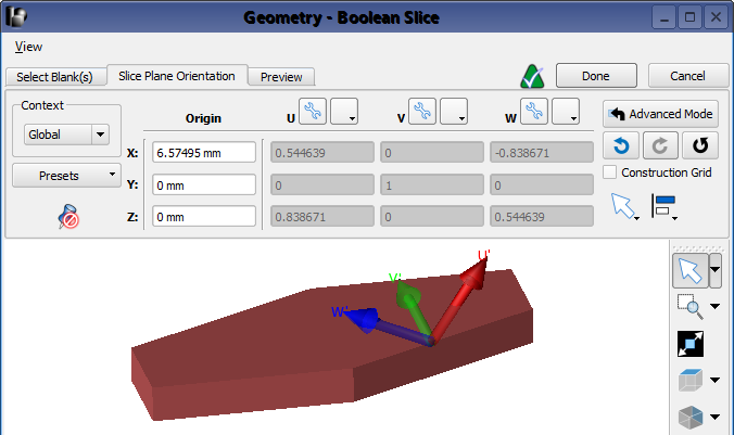
Define the plane that will slice an object by following these steps:
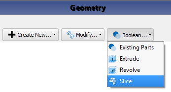
- In the Project Tree, right-click on the part to be sliced, then select Boolean ❯ Slice to open the Boolean Slice editor.
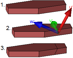
The UV plane is the cutting plane for the chop operation.
- Under the Slice Plane Orientation tab, define and orient the plane by either typing in the values or using the Direction Picking Tools in the lower right corner of the editor.
- Click the Preview tab to ensure the plane was created as expected.
Under the Preview tab, the Keep original blank(s) option will either keep both the original part(s) and the parts resulting from the Boolean Slice, or replace the original part(s) with the resulting parts when the box is checked or unchecked, respectively.
- Click Done to apply the changes and close the editor.
The Slice capabilities can also be accessed through the Boolean drop-down menu at the top of the Geometry window. When the editor is opened this way rather than by right-clicking in the Project Tree, users must begin under the Select Blank(s) tab by selecting the part. Multiple parts can be selecting using either the Shift or Ctrl key.