The parts meshing editor sets the mesh properties for an individual part, allowing users to adjust default settings as needed for increased accuracy. Meshing properties affect the application of a part's materials to the cell edges of the grid. A mesh is generated when either calculation files are written or the mesh is viewed.
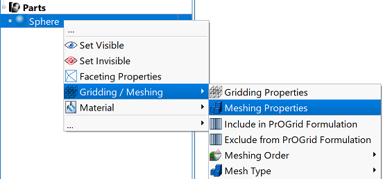
The meshing properties settings vary with the type of part—either a solid or voxel model—being modified. Users can access the Meshing Properties Editor by right-clicking on a part in the Project Tree and selecting Gridding / Meshing ❯ Meshing Properties.
Solid Model Editor

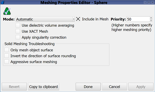
When the meshing properties editor for a part either created in XF or imported from a 3-D CAD model is opened, the available options include those relevant to solid models.
The Mode drop-down menu includes five options that determine what the mesh includes:
- Automatic: includes objects in both the electric and magnetic meshes based on their assigned properties. This default setting excludes parts with assigned free space.
- Meshing Disabled: disables meshing for objects considered unnecesssary during meshing operations. This setting reduces memory usage by removing the object from the computation.
- Electrical Meshing: includes the associated object in the electric mesh only.
- Magnetic Meshing: includes the associated object in the magnetic mesh only.
- Dual Meshing: includes the associated object in both the electric and magnetic meshes.
Three options are available with each of the modes:
- Use dielectric volume averaging: enables dielectric volume averaging for the associated object, provided it is assigned a dielectric material.
- Use XACT Mesh: enables XF's Accurate Cell Technology for the associated object.
- Apply singularity correction: enables singularity correction for the associated object, provided it is assigned a conductor material.
Selecting or deselecting the Include in Mesh option determines whether the object is included or excluded when calculating the mesh, respectively. This setting does not affect an object's meshing mode or meshing order. Users can also access this option by right-clicking on one or more selected objects in the Project Tree, then choosing Gridding / Meshing ❯ Include in Mesh.
The Priority setting either raises or lowers the part's meshing order by increasing or decreasing its priority value, respectively. Users can also access this option by right-clicking on a part in the Project Tree and choosing Gridding / Meshing ❯ Meshing Order, and adjusting up or down as needed.
The Solid Meshing Troubleshooting section contains three specialized options:
- Only mesh object surface: meshes the part's shell rather than its entire volume.
- Invert the direction on surface rounding: rounds the object inward toward its center when the object's edge falls on a cell's center rather than the cell's edge.
- Aggressive surface meshing: assigns the part's material to any cell edge it intersects regardless of the percent fill. This creates a more inclusive mesh around smaller features.
Five buttons appear across the bottom of both editors:
- Revert: discards changes and restores the editor's settings to the previous saved version.
- Copy to clipboard: copies the editor's applied settings, which users can paste to other individual parts.
- Done: saves the entered specifications and closes the editor.
- Cancel: discards the entered specifications and closes the editor.
- Apply: saves the entered specifications and leaves the editor open.
Voxel Model Editor

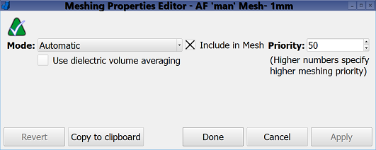
When the meshing properties editor for a voxel object is opened, the options are limited to those relevant for voxel models. The functionality described in the solid model editor is duplicated here for the available settings.
Voxel models are imported into XF by clicking File in the upper-left corner of XF, and then Import ❯ Voxel Object.
