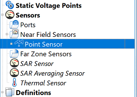
The  Point Sensor records data at its specified point-location within the simulation space. It is defined by either clicking on a geometric object with the picker tools, or by typing in a Cartesian 3-D expression. The associated point sensor definition specifies which data to collect at the location.
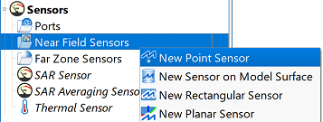
Users can create a point sensor by right-clicking on Near Field Sensors in the Project Tree, then selecting New Point Sensor. The editor across the top of the Geometry window consists of two tabs: Location and Properties.
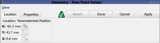
Under the Location tab, users can define the sensor's location by manually entering its coordinates into the editable X, Y, and Z fields, or using the picker tools ( ,
,  ,
,  ) to click on the desired location in the geometry window.
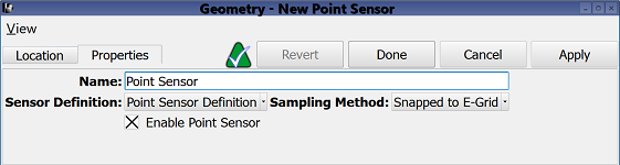
Under the Properties tab, users can enter a sensor identifier into the Name field, and specify the associated Sensor Definition by choosing from the current project's existing sensor definitions listed in the drop-down menu. A definition must accompany each point sensor in order to determine which time-domain data is collected at the specified point in space.
Users can also specify the Sampling Method by choosing from the drop-down menu. Selecting Snapped to E-Grid sets the location of the point sensor to the nearest E-grid cell vertex. A snapped point sensor's field components come from the cell whose lowest-index corner is defined by the snapped location of the sensor. Users should note that sensor location is therefore dependent on the grid definition.
Selecting Field Interpolation performs linear interpolation among the surrounding eight appropriate field value sample points in order to place the field components at the exact location of the point sensor.
Users can either enable or disable each point sensor by selecting or deselecting the Enable Point Sensor option, respectively.
Four buttons provide options for completing changes to the editor:
- Revert: discards changes and restores the previously saved settings.
- Done: closes the editor and saves the entered specifications, which are visible when the editor is re-opened.
- Cancel: closes the editor and does not save the entered specifications.
- Apply: saves the entered specifications but does not close the editor.