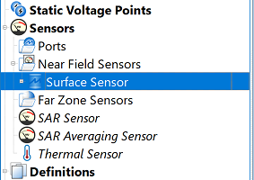
The  Sensor on Model Surface records data on the faces of a part. It is defined by clicking on one or more of a part's surfaces in the geometry window. The associated surface sensor definition specifies which data to collect on the surface.
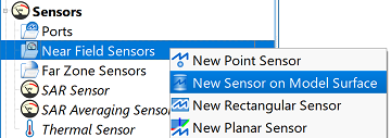
Users can create a sensor on model surface by right-clicking on Near Field Sensors in the Project Tree, then selecting New Sensor on Model Surface. The editor across the top of the Geometry window consists of three tabs: Select Model, Select Faces, and Properties.
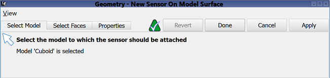
Under the Select Model tab, users can select the part on which to position the sensor by clicking on the desired solid part in either the geometry window or the project tree. Voxel geometry cannot be selected.
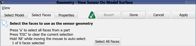
Selecting a model enables the Select Faces tab, where users can specify the face on which to attach the sensor. All faces of the chosen model are selected by default, so changes are only necessary if individual faces are desired.
Users can specify one or more faces by clicking on the desired location in the geometry window. The following commands assist with the selection process:
- Click the Select All Faces button to select all of a part's faces.
- Press a and click on the desired part in the geometry window to select all of its faces.
- Press esc to clear all selected faces.
- Press alt while mousing over a part in the geometry window to select faces beneath the cursor.
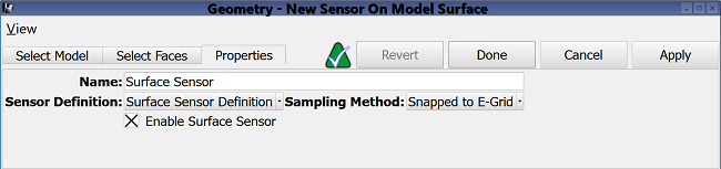
Under the Properties tab, users can enter a sensor identifier into the Name field, and specify the associated Sensor Definition by choosing from the current project's existing sensor definitions listed in the drop-down menu. A definition must accompany each surface sensor in order to determine which time- and frequency-domain data to collect across each surface.
Users can also specify the Sampling Method by choosing from the drop-down menu. Selecting Snapped to E-Grid sets the location of the surface sensor to the nearest E-grid cell vertex. A snapped surface sensor's field components come from the cell whose lowest-index corner is defined by the snapped location of the sensor. Users should note that sensor location is therefore dependent on the grid definition.
Selecting Field Interpolation performs linear interpolation among the surrounding eight appropriate field value sample points in order to place the field components at the exact location of the surface sensor.
Users can either enable or disable each surface sensor by selecting or deselecting the Enable Surface Sensor option, respectively.
Four buttons provide options for completing changes to the editor:
- Revert: discards changes and restores the previously saved settings.
- Done: closes the window and saves the entered specifications, which are visible when the window is re-opened.
- Cancel: closes the window and does not save the entered specifications.
- Apply: saves the entered specifications but does not close the window.