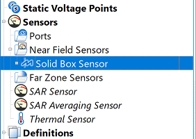
The  Solid Box Sensor collects data within the volume of a 3-D box in the simulation space. The associated solid sensor definition specifies which data to collect in the box.
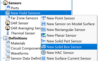
Users can create a solid box sensor by right-clicking on Near Field Sensors in the Project Tree, then selecting New Solid Box Sensor. The editor across the top of the Geometry window consists of three tabs: Orientation, Opposite Corner, and Properties.
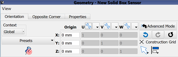
Under the Orientation tab, users can define the X, Y, and Z location of the origin, which serves as one corner of the box. The U', V', W' vector settings determine the orientation of the box within the simulation space. The advanced settings, direction picking tools, and alignment tools provide additional methods for adjusting all aspects of both the origin and vector orientations.
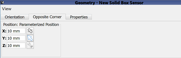
Under the Opposite Corner tab, users specify the second point of the box. Users can set this location by either manually entering its coordinates into the editable X, Y, and Z fields, or using the picker tools ( ,
,  ,
,  ) to click on the desired location in the geometry window.
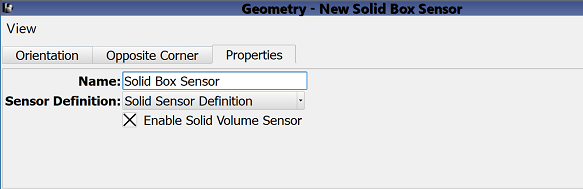
Under the Properties tab, users can enter a sensor identifier into the Name field, and specify the associated Sensor Definition by choosing from the current project's existing sensor definitions listed in the drop-down menu. A definition must accompany each solid box sensor in order to determine which time- and frequency-domain data to collect across each surface.
Users can either enable or disable each solid box sensor by selecting or deselecting the Enable Solid Volume Sensor option, respectively.
Four buttons provide options for completing changes to the editor:
- Revert: discards changes and restores the previously saved settings.
- Done: closes the window and saves the entered specifications, which are visible when the window is re-opened.
- Cancel: closes the window and does not save the entered specifications.
- Apply: saves the entered specifications but does not close the window.