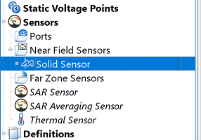
The  Solid Part Sensor records data within the volume of a selected part. It is defined by clicking on the part either in geometry window or the project tree. The associated solid sensor definition specifies which data to collect through the volume.
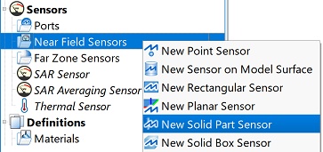
Users can create a solid part sensor by right-clicking on Near Field Sensors in the Project Tree, then selecting New Solid Part Sensor. The editor across the top of the Geometry window consists of two tabs: Select Model and Properties.
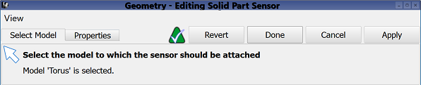
Under the Select Model tab, users can select the part on which to associate the sensor by clicking on the desired solid part in either the geometry window or in the project tree. Voxel geometry cannot be selected.
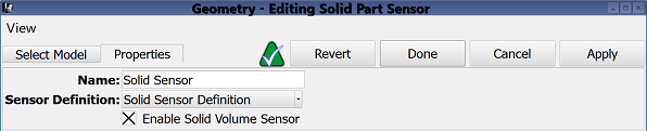
Under the Properties tab, users can enter a sensor identifier into the Name field, and specify the associated Sensor Definition by choosing from the current project's existing sensor definitions listed in the drop-down menu. A definition must accompany each solid sensor in order to determine which time- and frequency-domain data to collect within the specified volumetric space.
Users can either enable or disable each surface sensor by selecting or deselecting the Enable Surface Sensor option, respectively.
Four buttons provide options for completing changes to the editor:
- Revert: discards changes and restores the previously saved settings.
- Done: closes the editor and saves the entered specifications, which are visible when the editor is re-opened.
- Cancel: closes the editor and does not save the entered specifications.
- Apply: saves the entered specifications but does not close the editor.