August 9, 2022: The content below helps navigate the new features in this release. A full list of updates is available in the Reference Manual's Appendix.
Frequency Bands

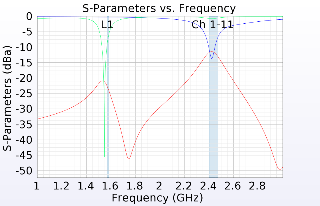
This release allows users to include bands with an finite-difference time-domain (FDTD) simulation, as well as specify a number of steady-state data samples to collect across a band. Users can choose from a library of commonly used, pre-defined frequency bands, or add a new band with customized specifications.
XF's create FDTD simulation window supports new syntax for specifying multiple steady-state frequencies:
- [start-value : end-value : increment]
- {start-value : increment : count}
- <start-value : end-value : count>
Users can find details about these two updates on Remcom's support site.
SAR Post-Processing

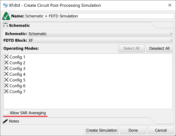
The average specific absorption rate (SAR) algorithms are decoupled from the FDTD simulation for accessibility during post-processing. The S-parameters tab of the create FDTD simulation window provides options for SAR averaging, and applying a circuit simulation during post-processing includes a setting that computes the average SAR.
These updates allows users to avoid re-running a full FDTD simulation while computing averaged SAR with a matching network, and enable a VOP compression workflow with MRI design.
Schematic Editor Updates

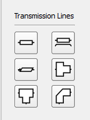
This release improves XF's schematic capability with multiple updates within its editor. Additional transmission line components, such as a microstrip line, microstrip step, microstrip tee, and microstrip bend, provide more accurate models, and an editable substrate list allows users to define individual substrates and specify which ones are available for use by transmission line components.
This updated functionality also supports an equation-based RLC component that mimics XF's circuit element optimizer (CEO) capability with increased flexability. Users can select the desired topology, choose a primary element, and define a component's behavior by editing it's associated equation.
Enhanced voltage source settings allow users to define a port number for labeling results and specify whether a source is active or inactive. The switch editor contains an editable field for either capacitance or resistance when the switch state is specified as open or closed, respectively.
Additionally, users can re-name the default operating mode, and navigate the operating mode list using the search functionality.
IEC/IEEE Standards
XF 7.10.1 is compliant with and passes all tests outlined in the international standards determined by the International Electrotechnical Commission (IEC) and the Institute of Electrical and Electronics Engineers (IEEE).
Additional Capabilities
This version introduces over 30 usability, performance, scripting, and other updates.
Here is a select list of modifications:
- Added circuit element optimizer (CEO) results capability to the schematic editor.
- Improved measuring tool to display the surface area of highlighted faces.
- Added circuit component visibility to the meshed representation.
- Included reason for FlexLM license denial.
- Added ability to separate output into individual runs in the simulations window.
- Included system and radiation efficiency type in the default graph title.
- Added hotkeys for geometry window default views.
- Added hotkeys for setting the visibility state of parts.
- Added ability to choose by name in a schematic XF block.
- Improved the user-interface (UI) for Optenni Lab post-processing.
- Added search capability to net and component tables in PCB import dialog.
- Provided an option to not re-import previously deleted parts during CAD merge.
- Resolved intermittent XFsolver crashing caused by a large number of GPUs relative to the size of the space.
- Corrected output file that was not saving the CEO version.
- Corrected default action for point sensor rotating B-field.
- Fixed chamfer and blend operations removing parameterization.


