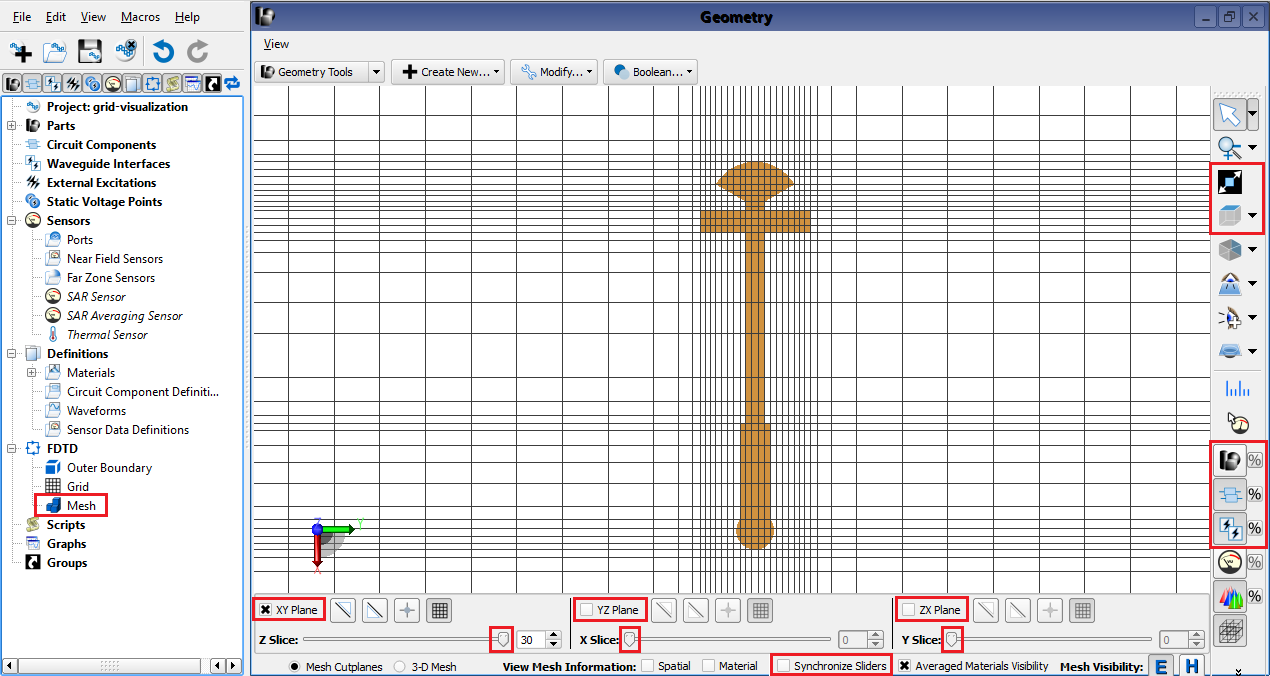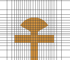
Visualizing the grid before running a simulation helps users align gridlines with geometry and achieve accurate results. XF's grid visualization tools include the meshing control panel capabilities, as well as part visibility and view orientation buttons.
Viewing the grid begins with the mesh controls that open across the bottom of the geometry window. Users can open this control panel by double-clicking on Mesh in the Project Tree, but it also opens immediately with certain changes in the main grid editor. While working in the main grid editor, users can view the grid as it adjusts to changes that have not yet been applied to the project.
The mesh controls include the following settings:
- When selected, the XY Plane, YZ Plane, and ZX Plane options each render the grid in the associated plane.
- The Z Slice, X Slice, and Y Slice sliders move grid slices from 0 to the maximum associated with each axis. Intermediate slices are unnecessary when using visibility buttons to confirm hidden part alignment.
- When selected, the Synchronize Slides option meshes geometry as a slider moves through it, causing a delay. Deselect this option for large geometry.
Once a grid plane is rendered, orient the view along one of the principle axes.
 : aligns the geometry with the axis selected from the drop-down menu.
- Ctrl+
 : cycles through the listed axis views beginning with the initial selection.
 - Shift+
 : rotates the view around the selected axis.
Re-position geometry and adjust the view:
 : zooms in on a part selected in the project tree.
- Scroll the middle mouse wheel to zoom in or out.
- Shift+ clicking and dragging moves geometry in its current plane.
Control visibility using sidebar buttons:
 : toggles all parts' visibility on and off. When off, selecting a part in the project tree renders it visible.
 : toggles components' visibility on and off.
 : toggles waveguide interfaces' visibility on and off.
