This example demonstrates XF's workflow for analyzing a matching network whose impedance changes in order to accomodate two antenna loading conditions. This is applicable to devices that use sensors—such as proximity sensors or accelerometers—in order to maximize performance in various use cases. When the sensors detect a human head, the matching network's dynamic component value changes for enhanced antenna performance.
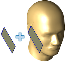
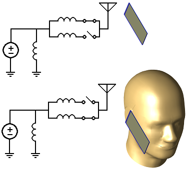
The antenna in this workflow example is designed for Band 13 from 746 MHz to 787 MHz. Its intrinsic impedance is simulated for two scenarios—one with its location in free space, and one with it next to the head. A matching network is applied during post-processing to view the matched performance and a switchable component changes the series inductor according to the loading condition.
The steps in the antenna design workflow form the basis for this project, however, this example applies the following modifications.
- The geometry includes both the phone and head models required for the two loading conditions.
- The grid extents settings ignore unmeshed parts.
- The head is either excluded or included from the mesh depending on the simulated configuration.
- Two FDTD simulations are created.
- A script simplifies the task of toggling the head's meshing properties and creating the two simulations.
- In post-processing, a schematic is created in order to analyze the matching network.
- The two simulations are loaded into a single FDTD block.
- A three-port switch is added.
- Two operating modes are added that define the switch states associated with the FDTD simulations.
Geometry
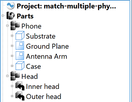
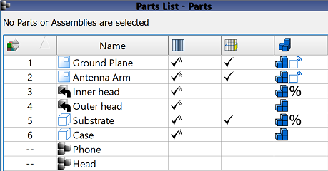
In order to analyze the two loading configurations in a single project, all geometry required for both configurations must be added to the parts list. In this example, both the phone and head models must be included.
Grid
For efficient RAM use during the simulation, the extents of the simulation space should include only the geometry of interest. In the free space simulation, the head is excluded from the mesh so the grid extents should omit it as well.
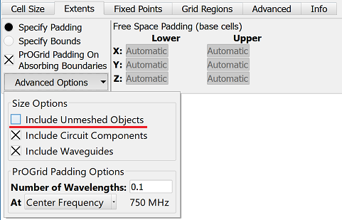
A simple way to resize the grid's extents based on the head's mesh settings is to ignore unmeshed objects when determining the grid's extents.
- Double-click on Grid in the Project Tree to open the main grid editor.
- Under the Extents tab, use the Advanced drop-down menu to deselect the Include Unmeshed Objects option.
- Click Done to close the editor.
Mesh
The head is included in the project but it is not required for the free space simulation. Rather than deleting it, it should be either included or excluded from the mesh as needed.
- Include the head by right-clicking on the Head assembly in the Project Tree and selecting Subparts ❯ Gridding / Meshing ❯ Include All Subparts from Mesh.
- Exclude the head by right-clicking on the Head assembly in the Project Tree and selecting Subparts ❯ Gridding / Meshing ❯ Exclude All Subparts from Mesh.
Simulation
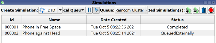
Two FDTD simulations must be created in order to determine the antenna's intrinsic impedance for each of the two loading conditions. S-parameters are collected in order to view the broadband response, and multiple steady-state frequencies are collected in order to assess system efficiency.
The following steps must be completed sequentially:
- Exclude the head assembly from mesh.
- Create a simulation for the phone in free space.
- Include the head in the mesh.
- Create a simulation for the phone next to the head.
Repeatable steps such as these are a good task for scripting.
Results
Please log in to view this content.
Remcom customers and those interested in our products may access this content after logging in.
Script
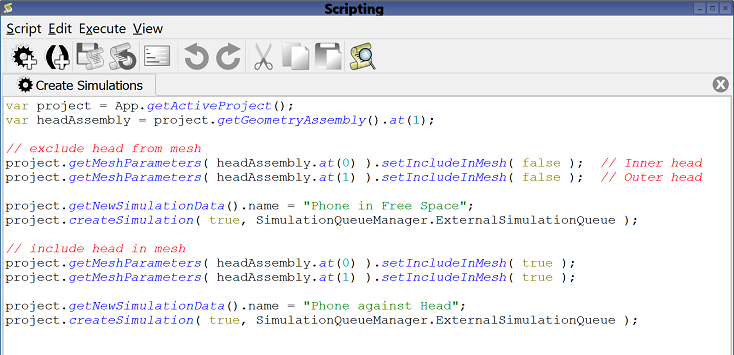
This example scripts the four step process of either including or excluding the head from the mesh and creating a simulation as outlined in the simulation section. Although impractical for a project with a single set of simulations, it would be beneficial in a design workflow with several antenna modifications.
XF's scripting capability supports the automation of all aspects of enabling and disabling multiple configurations, including material frequencies, bands, and sensors. If desired, users can contact Remcom Technical Support for assistance.