Modal Waveguide: Mode Converter | XFdtd
![]() Compute modal S-parameters between TE10 and TE20 modes.
Compute modal S-parameters between TE10 and TE20 modes.
![]() Compute modal S-parameters between TE10 and TE20 modes.
Compute modal S-parameters between TE10 and TE20 modes.
Related Pages: Modal Waveguide Interface, Faceting Properties
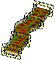
This tutorial focuses on setting up two modal waveguide interfaces and computing the broadband S-parameter results between the TE10 and TE20 modes. Additionally, an animation of the electric field results are viewed to see how the waveguide structure enables the conversion.
The modal waveguide structure consists of three segments, all of which were created with XF's modeling options. Each part utilizes the defined parameters, is assigned the PEC material, and has PrOGrid enabled. For the curved middle segment only, XACT is enabled and the faceting quality is set to high. A planar sensor requests steady-state electric fields through the simulation space. The waveform covers the project's frequency range of interest between 7.6 GHz and 9.4 GHz.
Modal waveguide interfaces are created for a structure that acts as a mode converter. For each interface, a waveguide port is identified and the mode number is specified. When creating a simulation, steady-state data is collected at a specified frequency of 8.5 GHz.
Broadband S-parameter results show the reflection coefficient and conversion from TE10 to TE20. The planar steady-state electric fields help visualize how the bend in the waveguide allows the conversion to happen.