A  Diode circuit component definition is an active component that allows users to model the nonlinear current-voltage characteristics of a PN junction.
Diodes should be used when only time-domain results are of interest. This is because diodes violate the assumptions of linear system theory, making it incorrect to apply either a Fourier or discrete Fourier transform to the time-domain results. A simulation containing a diode produces invalid frequency-domain results—including impedances, S-parameters, and steady-state far-zone fields—even if the time-domain results eventually decay to zero. The time-domain results are unaffected, and therefore are valid.

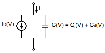
XFdtd's diode is modeled as a dependent current source, $I_D(V)$, in parallel with a nonlinear capacitor, $C(V)$, both of which are dependent upon the voltage. The nonlinear capacitance is primarily set by the depletion region capacitance, $C_j(V)$, when the PN junction is reverse biased, while the diffusion capacitance, $C_d(V)$, is dominant when the PN junction is forward biased. The dependent current source accounts for the transport of electrons and holes across the PN junction.
The dependent current source and the nonlinear capacitor are expressed using the following equations:
\begin{eqnarray}
I_D(V) &=& I_s \left(exp \left(\frac{V}{nV_T}\right)-1\right) & \qquad {\bf where} \quad V_T = \frac{kT}{q} \\
C(V) &=& \frac{\tau_DI_s}{nV_T} \left(exp \left(\frac{V}{nV_T}\right)\right) + C_{jo} \left(1 - \frac{V}{V_j}\right)^{-M} & \qquad {\bf if} \quad V\lt(FC \cdot V_j) \\
&\,&\frac{\tau_DI_s}{nV_T} \left(exp \left(\frac{V}{nV_T}\right)\right) + \frac{C_{jo}}{F_2} \left(F_3 + \frac{MV}{V_j}\right) & \qquad {\bf if} \quad V\ge(FC \cdot V_j)
\end{eqnarray}
where
$V $ = instantaneous cell edge voltage
$I_s $ = saturation content
$n $ = emission coefficient
$V_j $ = junction potential
$C_{jo} $ = depletion capacitance at zero bias
$\tau_D $ = sum of transit time for holes and electrons
$M $ = junction grading coefficient
$FC $ = coefficient that determines when the junction is heavily forward biased
$F_2 = (1 - FC) ^{1+M}$
$F_3 = 1 - FC (1+M)$

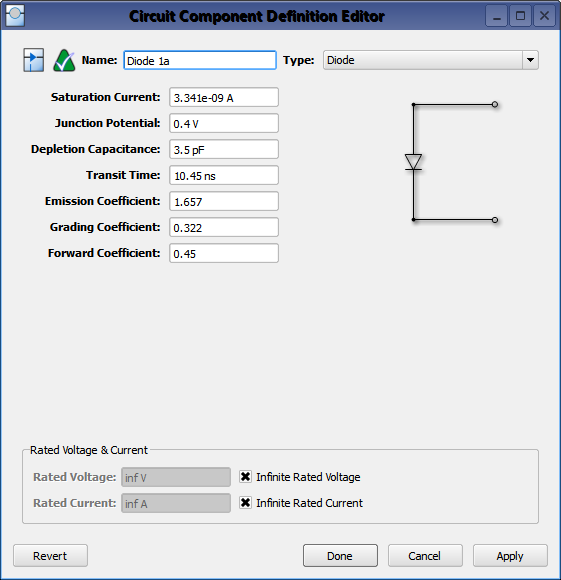
Double-clicking on a circuit component definition in the Definitions branch of the Project Tree opens the Circuit Component Definition Editor, where a diode is created by choosing Diode from the Type drop-down menu.
A diode's polarity is controlled using the +/- endpoints on its associated circuit component.
Rated Voltage & Current settings apply to electrostatic discharge (ESD) analysis. Both Rated Voltage and Rated Current default to infinity, but users can change either value by unchecking the associated box and entering the desired value or expression. These settings do not affect energy propagation through the component, but XF checks the voltage and current at each timestep during a simulation to see if they exceed the rated values. Users can adjust these settings to flag components that are likely to experience damage or failure during a simulation.
![]() Diode circuit component definition is an active component that allows users to model the nonlinear current-voltage characteristics of a PN junction.
Diode circuit component definition is an active component that allows users to model the nonlinear current-voltage characteristics of a PN junction.

