
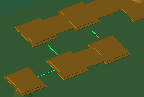
 Circuit Components are discrete components, such as resistors, capacitors, inductors, voltage sources, current sources, switches and diodes. Voltage and current sources are locations at which the electric field is modified by adding an input waveform.
A circuit component is always paired with a circuit component definition. The former specifies the component's location in space, and the latter identifies it as a resistor, voltage source, or switch.
Use Cases
Circuit components and their associated definitions support a wide range of use cases:
- A single voltage source exciting a microstrip transmission line that is feeding an antenna.
- Numerous voltage sources with varying phases exciting an antenna array.
- Resistors, capacitors, or inductors providing a matching circuit for an antenna.
- Feeds and passive loads simulating the behavior of MRI coils.
Create and Edit
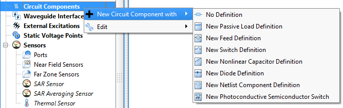
Create a circuit component by right-clicking on Circuit Components in the Project Tree and selecting New Circuit Component with, and then choose from the drop-down menu options to open the editor. Selecting a new definition option adds a definition to the Definitions branch of the Project Tree.
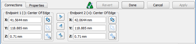
The Circuit Component editor consists of two tabs: Connections and Properties. Under the Connections tab, Endpoint 1 and Endpoint 2 specify the location of the component in the global coordinate system. Users can manually enter each X, Y, and Z value into its corresponding field, or use the picker tools ( ,
,  ,
,  ) to specify the endpoints within the geometry window.
The (-) and (+) indicators accompany the endpoints' text for both feed and diode circuit component definitions, and are equivalent to the black and red cables of a waveform generator found in a lab setting.
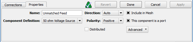
Under the Properties tab, the component's name, direction, and polarity is defined:
- Name: a user-defined descriptor that will be referenced when creating simulations and analyzing results.
- Component Definition: associates electromagnetic properties with the component.
- Direction: orients the component along the selected x-, y-, or z-axis, or allows XF to determine the orientation based on the endpoints when the auto option is selected.
- Polarity: sets the positive or negative value associated with both endpoints.
- Distributed: spreads the component across the width of the trace it is attached to.
- Include in Mesh: includes the component in the mesh.
- This component is a port: assigns the component as a port, prompting XF to add a port sensor at the specified location.
- Advanced: displays additional controls that affect how the computational grid is generated in the vicinity of the component.
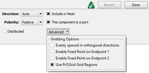
Advanced gridding options can be accessed through the drop-down arrow:
- Evenly spaced in orthogonal directions: applies the same cell size in the two directions perpendicular to the component's axis.
- Enable Fixed Point on Endpoint 1: inserts a fixed point at the circuit component's first endpoint.
- Enable Fixed Point on Endpoint 2: inserts a fixed point at the circuit component's second endpoint.
- Use PrOGrid Grid Regions: applies PrOGrid boundary refinements to reduce grid cell sizes near the circuit component.
Applying the Use PrOGrid Grid Regions setting resolves the distance between the two component endpoints by a minimum of one grid cell and adds boundary refinements on the line defining the circuit component. These refinements reduce cell sizes in directions perpendicular to the circuit component. A circuit component's boundary refinements are determined by both the main grid's Good Conductor Boundary Refinement Ratio and Boundary Refinement Number of Cells values.
Tag
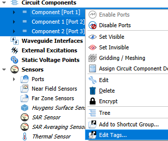
User-created tags allow users to quickly filter the list of circuit components in the Project Tree. Tags follow a parent/child hierarchy, so users can create different groupings and subgroupings for quick and complex filtering.
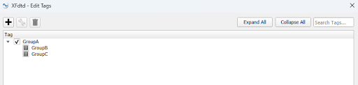
Right-clicking the selected circuit components and choosing Edit Tags... opens the Edit Tags dialog, where users can:
- Create a new tag, optionally with an already-created tag as its parent.
- Add an existing tag to the selected circuit components.
- Edit an added tag's name.
- Delete a tag from the selected circuit components.
- See which tags are fully shared (fully checked) or not fully shared (gray box) by the selected circuit components.
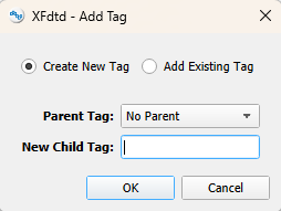
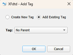
The Add Tag dialog provides two options: Create New Tag defines a new tag and optionally assigns an existing tag as its parent, while Add Existing Tag applies an already-created tag to the selected circuit components.
Filter
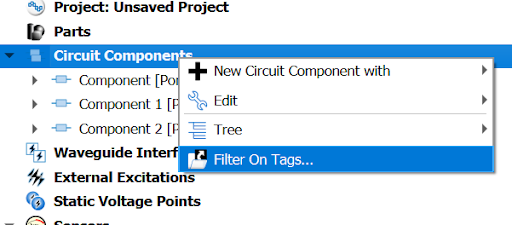
Users can open a menu showing the available tags either by right-clicking on Circuit Components in the Project Tree and selecting Filter On Tags..., or by right-clicking the View Circuit Components button.
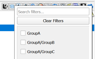
Clicking a tag in the menu applies it to the list of circuit components as a filter, so only the circuit components with that tag are shown. Circuit components with a tag that has a parent are automatically tagged with that parent as well, and therefore appear when the parent is applied as a filter.
The menu automatically updates to show only the applicable tags based on the tags already selected. In other words, once a tag is selected, any tags that do not belong to the remaining circuit components are hidden.
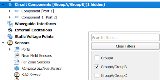
When a tag is used as a filter, the Circuit Components branch of the Project Tree updates to show which tags are being used and how many circuit components are hidden.
Simulate
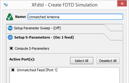
Users can set up a simulation either with or without S-parameters. When S-parameters are enabled and more than one port is selected, the simulation will contain one run for each selected port. In each run, one of the selected ports is active and all other sources are inactive.
When S-parameters are disabled, all ports will be active with the power specified in their circuit component definition.
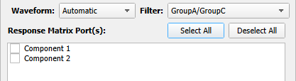
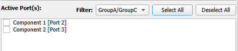
Tags can also be used during FDTD and response matrix simulation creation to filter the list of available ports. The list updates to show only the ports whose circuit components carry the selected tag.