A  Passive Load circuit component definition includes a resistor (R), inductor (L), and capacitor (C) in various arrangements.
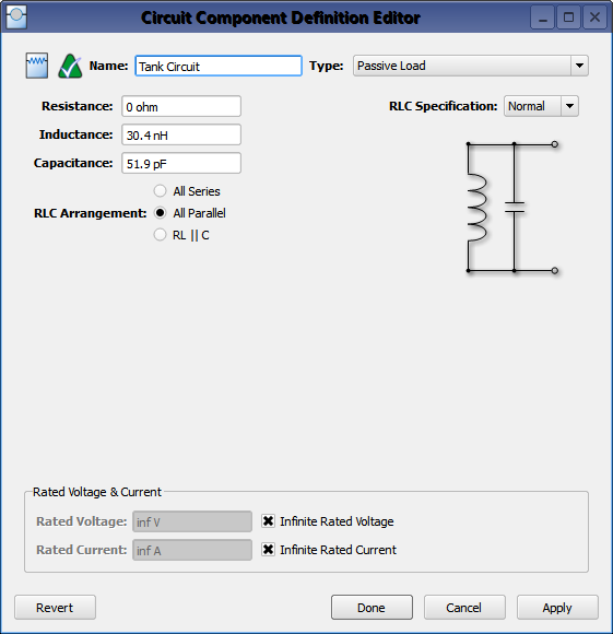
Double-clicking on a circuit component definition in the Definitions branch of the Project Tree opens the Circuit Component Definitions Editor, where a passive load is created by selecting Passive Load from the Type drop-down menu.
The RLC Arrangement controls provide three configuration options:
- All Series: places a resistor, an inductor, and a capacitor in series.
- All Parallel: places a resistor, inductor, and capacitor in parallel with one another.
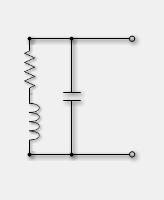
- RL || C: places the series combination of resistor and inductor in parallel with a capacitor.
The RL || C arrangement is useful for modeling a non-ideal inductor that includes the effects of wire resistance and self-capacitance.
The RLC elements are optional in both the All Series and All Parallel configurations, and can be removed by setting the appropriate value to zero. All of the RLC elements are required when using the RL || C configuration, so all of the element values must be greater than zero. Regardless of the configuration, the resulting impedance is applied to the finite-difference time-domain (FDTD) mesh at the associated circuit component's location.
The RLC values can be specified in two ways, both of which result in a single set of RLC values being used for simulation. The first RLC Specification method, Normal, is appropriate when the equivalent circuit can be represented as a constant value for each RLC element over all frequencies.
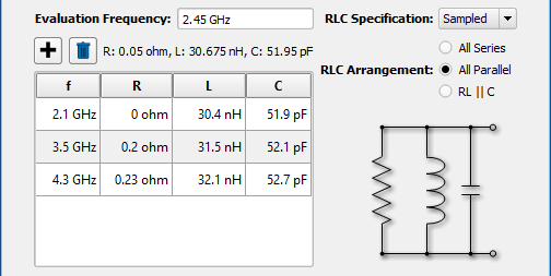
The second RLC Specification method, Sampled, is appropriate when the equivalent RLC values are frequency dependent. When Sampled is selected, RLC values are specified at discrete frequencies using the  button. Although multiple sets can be specified, the Evaluation Frequency dictates which single set of RLC values is used during the simulation. The values displayed above the table will be applied during simulation, and are determined using linear interpolation when the Evaluation Frequency is between sample points. This frequency should be near the middle of the frequency range of interest in order to match the impedance response for the entire band as closely as possible.
Rated Voltage & Current settings apply to electrostatic discharge (ESD) analysis. Both Rated Voltage and Rated Current default to infinity, but users can change either value by unchecking the associated box and entering the desired value or expression. These settings do not affect energy propagation through the component, but XF checks the voltage and current at each timestep during a simulation to see if they exceed the rated values. Users can adjust these settings to flag components that are likely to experience damage or failure during a simulation.