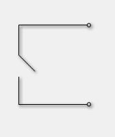
A  Switch circuit component definition is an active component that allows a change in the geometry's configuration during a calculation. It is defined by specifying an initial state—either open or closed—as well as the time at which the transition begins and the duration of time that the action will last.
Background
Switches are updated during a finite-difference time-domain (FDTD) simulation by modifying the instantaneous electric field
\begin{equation} E\big|^n = \chi\big|^nE\big|^n \end{equation}where $\chi\big|^n$ represents the state of a switch at timestep, $n$. The electric field at the switch location is first calculated as though the switch were not present. That value is then multiplied by zero or one for a closed or open switch, respectively. Because the initial calculation omits the switch state, the switch's function depends on the material that exists at the mesh location. Given that $E=0$ for perfect electric conductors, a closed switch acts as a wire.
During a transition, a Gaussian function is applied in order to smooth the transition from either zero to one (as a closed switch opens), or one to zero (as an open switch closes). The transition should take place over approximately 60 timesteps in order to reduce the amount of high-frequency transient signals being introduced into the simulation space.
Switches should be used when only time-domain results are of interest. This is because switches violate the assumptions of linear system theory, making it incorrect to apply either a Fourier or discrete Fourier transform to the time-domain results. A simulation containing a switch produces invalid frequency-domain results—including impedances, S-parameters, and steady-state far-zone fields—even if the time-domain results eventually decay to zero. The time-domain results are unaffected, and therefore are valid.
Controls
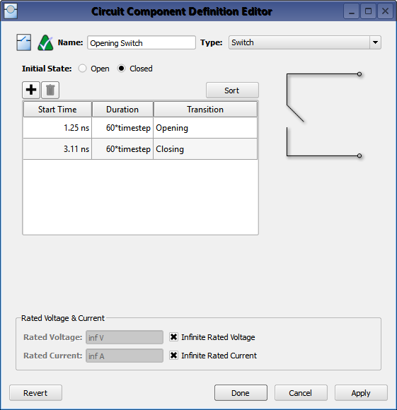
Double-clicking on a circuit component definition in the Definitions branch of the Project Tree opens the Circuit Component Definitions Editor, where a switch is created by choosing Switch from the Type drop-down menu. The switch's properties are defined by selecting either Open or Closed to set the switch's initial state, and then clicking  to add a transition. Enter the Start Time and Duration by double-clicking on the default values and typing into the highlighted space. XF generates the Transition value based on the Start Time of each transition, and the Sort button arranges the transitions from the earliest to the latest occurring state.
Add subsequent entries to the initial definition by clicking and following the same process as when defining the original transition.
to add a transition. Enter the Start Time and Duration by double-clicking on the default values and typing into the highlighted space. XF generates the Transition value based on the Start Time of each transition, and the Sort button arranges the transitions from the earliest to the latest occurring state.
Add subsequent entries to the initial definition by clicking and following the same process as when defining the original transition.
Rated Voltage & Current settings apply to electrostatic discharge (ESD) analysis. Both Rated Voltage and Rated Current default to infinity, but users can change either value by unchecking the associated box and entering the desired value or expression. These settings do not affect energy propagation through the component, but XF checks the voltage and current at each timestep during a simulation to see if they exceed the rated values. Users can adjust these settings to flag components that are likely to experience damage or failure during a simulation.