 Nodal Waveguide Interface is well suited for TEM and quasi-TEM transmission lines, such as microstrips, striplines, and differential pairs. When S-parameters are requested, a user-defined reference impedance generates a mismatch and single-ended renormalized S-parameters are computed for each pin. Alternatively, each pin can be excited with a nodal field distribution for time-domain crosstalk analysis.
Use Cases
There are two primary use cases for the nodal waveguide interface:
- Computing renormalized S-parameters that include a mismatch at the source.
- Applying a nodal excitation to a set of pins, without collecting S-parameters.
In the first use case, the excitation will not exhibit a reflection at the interface because it is matched to the transmission line being fed. As a post processing step, a mismatch is added to compute renormalized S-parameters by applying a user-defined reference impedance.
In the second use case, for transmission lines with only one signal conductor—microstrips and striplines—there is no difference between the modal and nodal waveguide interfaces because the nodal excitation and its results are equivalent to that of the modal excitation. For differential pairs and other multi-pin transmission lines, however, the nodal waveguide interface identifies individual pins and applies a single-ended nodal excitation to them.
Create and Edit
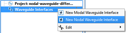
Open the nodal waveguide editor across the top of the Geometry window by right-clicking on the Waveguide Interfaces branch of the Project Tree and choosing New Nodal Waveguide Interface, or by double-clicking on an existing waveguide within the Project Tree.
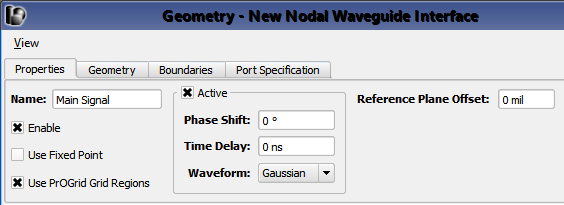
Under the Properties tab, basic properties of the waveguide interface can be defined:
- Name: a user-defined descriptor that will be referenced when creating simulations and analyzing results.
- Enable: includes the waveguide interface in the simulation. Unchecking Enable effectively removes an interface from a project without deleting it, so it is available for use later.
- Use Fixed Point: adds a fixed point to the grid in the plane of the interface.
- Use PrOGrid Grid Regions: includes the interface in the PrOGrid formulation which adds boundary refinements to each of the four edges that make up the rectangle of the waveguide interface. These refinements reduce cell sizes near the waveguide interface in both the propagation direction and the transverse directions. Boundary refinements for waveguides are consistent with the main grid editor�s good conductor boundary refinement ratio and boundary refinement number of cells settings.
- Active: allows pins to be excited. Uncheck Active to use the waveguide interface as a matched termination only.
- Phase Shift: phase shift applied to the associated waveform, but only if the waveform is a sinusoid.
- Time Delay: applied to the associated waveform, but only if the waveform is not a sinusoid.
- Waveform: associated waveform definition. The selected waveform will be applied to active pins.
- Reference Plane Offset: a positive value moves the reference plane for the S-parameters computation along the waveguide's propagation direction. This is useful in cases where it is inconvenient to position the interface plane at the precise location where S-parameters should be computed. Users should note that this assumes there is no change in waveguide propagation characteristics between the interface plane and reference plane, such as would occur due to a change in waveguide cross sectional geometry.
Users should note that either Phase Shift or Time Delay will be applied depending on whether or not the waveform is sinusoid.
The Geometry tab provides tools for specifying the location, size, and propagation direction of the interface. The Boundaries tab is used to specify the behavior of the four interface edges. These two tabs are identical to the tabs in the modal waveguide interface.
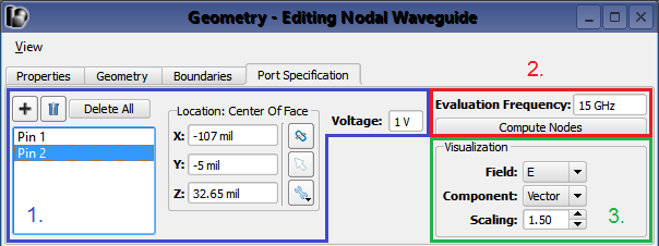
The nodal waveguide editor's Port Specification tab allows users to create ports corresponding to conductor pins or traces of the waveguide. One port must be created for each pin or trace that is not electrically connected to the waveguide's interface boundary.
There are three groups of controls:
- Pin specification.
- Field computation.
- Field visualization.
 and
and  buttons, respectively. Each signal conductor requires one corresponding pin. For example, a microstrip will have one pin while a differential pair will have two. Enter the location of each pin in the X, Y, and Z fields or by using the picker tools (
 ,
,  ,
,  ) to select geometry.
The Voltage field allows an excitation voltage to be set for the selected port's conducting pin or trace. Users should note that this voltage is only used when the nodal waveguide is active and when S-parameter computation is disabled.
Once the pins are defined, an eigensolver finds the corresponding field distribution based on the mesh in the cross section of the waveguide. Set the Evaluation Frequency within the operating range of the waveguide and click Compute Nodes to determine the field distributions.
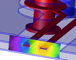
The Visualization settings render the nodal field distributions in the Geometry window for the selected pin.
Simulate
Set up a simulation either with or without S-parameters—according to the use case—when nodal waveguides are exciting the space. Nodal waveguides will act as a matched termination when they are defined, but not active.
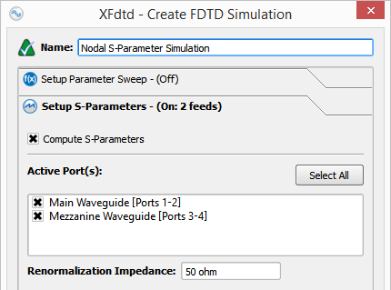
When collecting S-parameters, users should select each nodal waveguide in the Setup S-parameters tab and specify the Renormalization Impedance. This will generate the full renormalized S-parameter matrix for each of the pins in the project.
When not collecting S-parameters, uncheck Compute S-parameters. In the simulation, each pin will be excited with the voltage specified under the Port Specification tab in the nodal waveguide editor.