XF's waveguide interfaces launch a modal excitation into the simulation space. Each excitation has a field distribution associated with it and the interface's geometry defines the 2-dimensional area that launches the excitation.
Controls
The Geometry tab in the new waveguide interface editor allows users to define the size and location of the waveguide by choosing a location, orientation (via the propagation direction), and extent.
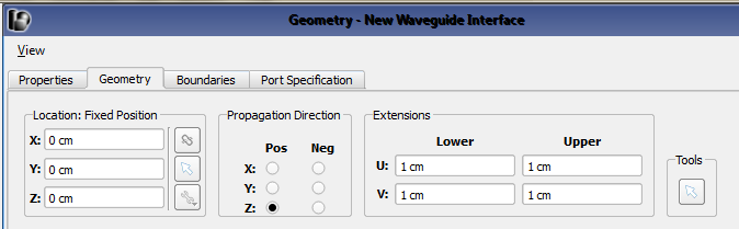
The Location values define where the waveguide interface is positioned in the simulation space, and it is typically placed at the end of the waveguide structure or transmission line it is feeding. The options allow users to manually enter the points using the X, Y, and Z spaces provided, or use the picker tools ( ,
,  ,
,  ) directly to the right of them. From top to bottom, the buttons detach the point from the geometry it is attached to, select a reference point on existing geometry, and access advanced options, respectively. The advanced options are available after a point has been chosen, and include Parametric Coordinates and Offsets. When the point is attached, the interface will change location to follow the part it is attached to if that part is moved to a different location within the geometry. Users should note that the point does not have to be the actual center of the waveguide cross section. The location and extensions are used to locate the interface rectangle.
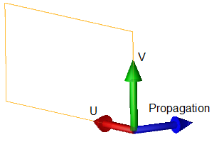
The Propagation Direction defines the orientation of the interface rectangle using the radio buttons for positive and negative X, Y, and Z positions. The local coordinate system's blue arrow in the Geometry window reflects the selected direction.
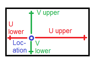
Extensions control the size of the waveguide interface. These values and the Location should enclose the energy that is launched from the waveguide. The Tools button enables the user to simultaneously pick the Location and Propagation Direction by clicking on the part within the Geometry window.
Recommendations
Waveguides with conducting boundaries on all transverse sides, such as the classic rectangular, circular, and coaxial waveguides, should have an interface size that encloses the waveguide fields completely.
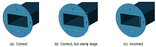
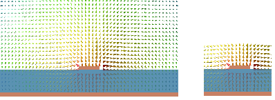
Waveguides that have one or more open sides, such as a microstrip, stripline, or coplanar waveguide, require an interface size large enough to enclose the strongest fields so that it may properly terminate the waveguide and modes may be properly computed. If the interface is too small, it may be impossible to compute the desired mode with accuracy or the fields will not have decayed sufficiently before reaching the interface boundary. If the interface is too large, additional nonphysical modes may be produced or it may interfere with the surrounding geometry.
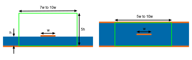
The following images give recommended interface sizes for some common structures based on empirical results. The first figure shows the interface for a microstrip with $w \simeq h.$ As $w$ becomes small compared with $h$, the most intense fields tend to stay near the vertical space above and below the trace. If $w > h$, the horizontal dimension of the interface may need to be increased to around $10w$.
The second figure shows the interface for a stripline. The lower value of the interface width is for $w \leq h$. The height of the interface should be set so that the horizontal sides of the interface are in the metal ground plane.
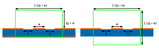
The following images show the interface for grounded and ungrounded coplanar waveguides. For the grounded case, the lower horizontal edge of the interface is in the ground plane. For the ungrounded case, the interface extends the same distance below and above the plane of the conductors.
For other open-ended structures, keeping the interface sides 5 x (maximum structure dimension) from the structure is a fairly conservative first choice. Users can verify that an interface is large enough by viewing the fields for the chosen mode and seeing that the fields do indeed drop off significantly by the time they reach the outer edges of the interface.