Project properties allow users to define the frequency range and display units for the entire project, as well as modify a specialized set of project attributes. This window opens everytime a new project is created because users should set the frequency range of interest as the first step in the workflow for any new project.
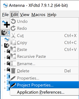
Users can access the Project Properties Editor by clicking Edit ❯ Project Properties in the upper-left corner of XF. The uneditable Name and Project Path fields at the top of the editor display the current project's name and location on disk once it is saved, respectively.
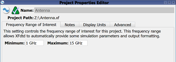
Frequency Range of Interest
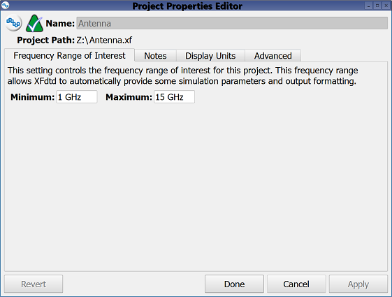
The Frequency Range of Interest tab allows users to define a frequency range for analysis. The finite-difference time-domain (FDTD) method enables a broadband waveform to cover this entire range in a single simulation. Users can set the frequency range by entering the lowest and highest desired frequencies as the Minimum and Maximum values, respectively.
Defining the frequency range is the recommended first step in setting up a project because it impacts several other aspects in the project. The frequency range is used to specify the waveform, determine cell sizes in the grid, determine good conductor materials, set simulation parameters, and limit bounds of frequency-domain output graphs.
Users can enter a parameter for one or both of the values.
Notes
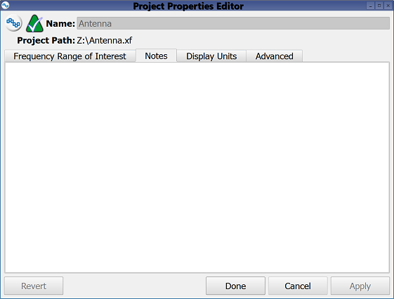
The Notes tab provides space for users to attach memos to a project, such as a brief description of its specifications for later reference.
When opening an existing project, notes appear as the Description in the Project Information section of the Open Existing Project window. The notes are editable in the project properties window once the project is opened.
Display Units
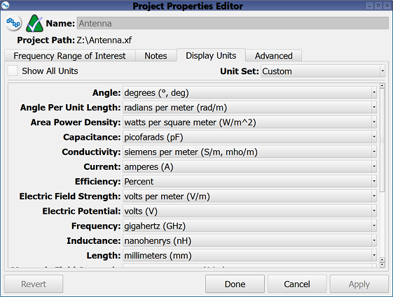
The Display Units tab defines the units of measure applied throughout the application. If a numeral is entered into a field without a specified unit, then the unit defined in this tab for that type of measurement is applied.
Selecting the Show All Units option lists every available unit setting below. Unchecking this option displays only the settings relevant to the current project.
The Unit Set drop-down menu includes the XFdtd Default and Custom settings, which users can apply to individual parameters, as well as the known measurement systems SI Metric, Gaussian Metric (CGS), and US Customary.
Advanced
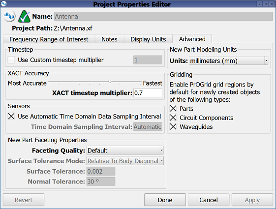
The Advanced tab settings affect simulation, as well as newly created parts. Users can change the project's default timestep in the Timestep section by checking the Use Custom timestep multiplier option and entering the desired value in the enabled field. The entered value is multiplied by the timestep computed from the grid in order to determine the applied timestep. This is necessary only in rare instances of instability associated with certain materials, so users should not edit this setting unless recommended by Remcom Technical Support.
The XACT Accuracy section provides additional control of the timestep when XACT is enabled for any part in a simulation. By default, XF maintains numeric stability during computation by reducing the simulation timestep for increased accuracy at the expense of run time. The XACT timestep multiplier sets the maximum amount of timestep reduction in order to limit the simulation run time as shown by the corresponding slider. Increasing or decreasing the 0.7 default value either reduces or improves accuracy, respectively.
The Sensors section defines how often time domain data is sampled during a simulation. By default, the selected Use Automatic Time Domain Data Sampling Interval setting determines the sampling rate in order to prevent aliasing of frequency-domain output. Unchecking this setting allows users to define the Time Domain Sampling Interval that sets the sampling rate for sensors that are not individually defined.
The New Part Faceting Properties section defines parts created after its specifications are applied to the project. The Faceting Quality drop-down menu includes the Default, Medium, High, and Custom options, which affect the overall quality of modeled surfaces. Higher quality slows rendering speed but produces a smoother surface. The Custom setting allows users to adjust the surface tolerance by selecting a mode and specifying a value.
There are two Surface Tolerance Mode options:
- Relative to Body Diagonal: specifies the tolerance as a ratio.
- Pure Number: specifies the tolerance as a distance.
An explanation of these settings is available on the faceting properties page.
The New Parts Modeling Units section defines the modeling units applied to parts created after the setting is applied to the project. Users can choose the desired option from the Units drop-down menu.
The Gridding section enables PrOGrid grid regions for parts created after the setting is applied to the project. Selecting one or more of the Parts, Circuit Components, and Waveguides options enables PrOGrid grid regions for the associated objects.
Four buttons provide options for completing changes to the project properties:
- Revert: discards changes and restores the previously saved settings.
- Done: closes the window and saves the entered specifications, which are visible when the window is re-opened.
- Cancel: closes the window and does not save the entered specifications.
- Apply: saves the entered specifications but does not close the window.