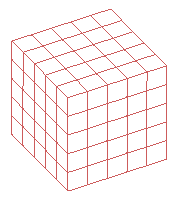
The mesh view controls offer a preview of the mesh and assist with grid visualization prior to simulation. The grid defines how the simulation space is discretized into cells, while the mesh specifies which material properties are associated with each cell edge. The grid and mesh comprise the geometric information passed to the calculation engine, so it's critical that they accurately represent the 3-D CAD geometry.
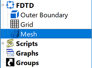
Users can open the meshing controls across the bottom of the Geometry window by double-clicking on Mesh in the Project Tree. Clicking the  button in the sidebar also opens the meshing controls and displays the most recently generated mesh. When editing the grid, the preview adjusts to changes that have not yet been applied to the project.
Users can control the visibility of mesh materials by right-clicking on a material in the Definitions branch of the Project Tree and selecting either Set Visible or Set Invisible. This is particularly useful when visualizing a 3-D mesh with one material obstructing the view of another.
Two viewing modes are available in the lower-left corner of the control panel: Mesh Cutplanes and 3-D Mesh.
Mesh Cutplanes
The Mesh Cutplanes mode creates slices of the mesh in the three primary planes, which users can render either individually or simultaneously using the associated checkboxes.

Each selected XY Plane, YZ Plane, or ZX Plane option enables its associated Z Slice, X Slice, or Y Slice slider, respectively. Each slider moves the mesh plane from 0 to the maximum associated with that axis and the adjacent value corresponds to its movement between those two positions.
Each selected plane also enables five buttons:
 : cut away solid geometry on the negative side of the associated mesh slice.
 : cut away solid geometry on the positive side of the associated mesh slice.
 : toggle viewing edges normal to the associated mesh slice.
 : toggle viewing cell edges assigned the free space material along the associated axis.
 : move the mesh slice to the location selected in the geometry window.
When is selected, tool options appear in the geometry window's on-screen display.
Checking or unchecking the View Mesh Information settings either shows or hides project details in the geometry window's on-screen display, respectively.
- Spatial: information includes the Index, Length, and Type of the Mesh Edge; as well as the X, Y, and Z coordinates of both the Grid Node Position and the Mouse Position.
- Material: the name and percentage of each material associated with the gridline at the mouse location.
- Part: the geometry name associated with the gridline at the mouse location.
Two adjacent checkboxes provide additional meshing options:
- Synchronize Sliders: when selected, a cutplane's movement is visible in the geometry window as its slider is adjusted.
- Averaged Materials Visibility: when selected, materials with dielectric volume averaging enabled are visible.
For large meshes, it is desirable to disable slider synchronization and averaged material visualization because the processing time to compute and render this data inhibits usabiliy.
The  and
and  Mesh Visibility buttons render the electric and magnetic mesh components, respectively.
3-D Mesh
XF's 3-D visualization helps users verify that the meshed geometry accurately represents the CAD geometry, and is well suited for checking the connectivity of antennas or transmission lines that cross multiple cutplanes. The 3-D Mesh mode allows users to either choose from four visibility settings or render a cropped view.

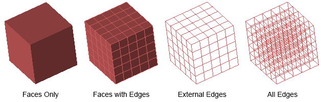
A single finite-difference time-domain (FDTD) cell contains 12 cell edges and six faces, which are rendered according to the 3-D Mesh Viewing Modes drop-down menu selection. The 3-D Off option hides the rendered mesh from view.
The visible edges and faces vary with each of the four modes:
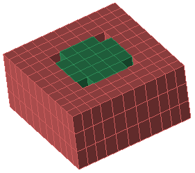
A face without a dominant color is rendered as a hole when the viewing mode includes faces. This is because XF cannot assign more than one color to a single face, and cannot eliminate a color by determining its value relative to another color. Adjacent cell edges of different colors create a hole where a face belongs, as shown in the image, where each of the four holes has two green cell edges and two red cell edges.
The holes do not generate an error during the FDTD simulation because the fields are computed on cell edges. The 3-D mesh face colors are for visualization purposes only.
Rendering the entire mesh is unnecessary for users wanting to verify only a specific region. Unchecking the Entire Mesh option enables additional settings and allows users to view a cropped area by defining a bounding box.
There are two methods for specifying a cropped view:
- Click and drag the green, blue, and red arrows in the Geometry window.
- Select one or more parts using Ctrl+) as needed, and then click the Bound to Selection button.
Users can store a cropped region by clicking the  button, and choose from previously saved regions using the drop-down arrow.