A user-defined antenna (UAN) file contains antenna pattern information in text format that users can create and read for use in post-processing applications. The *.uan file format is unique to Remcom and ideal for sharing data across its suite of design and electromagnetic simulation products, including XFdtd®, Wireless Insite®, XGtd®, WaveFarer®.
UAN File Structure

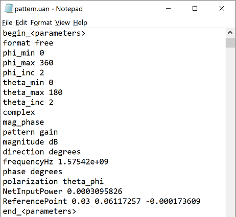
Although the *.uan file supports multiple formats, XF writes the complex output in one format only. The *.uan file begins with text concerning parameters. The theta-phi coordinate system provides definitions relative to the x-, y-, and z-axes.
The format free text line is of no significance to the file's content, but explanations for the remaining lines are as follows:
- phi_min: minimum phi observation angle in degrees.
- phi_max: maximum phi observation angle in degrees.
- phi_inc: phi observation angle increment in degrees.
- theta_min: minimum theta observation angle in degrees.
- theta_max: maximum theta observation angle in degrees.
- theta_inc: theta observation angle increment in degrees.
- complex: data consists of complex numbers.
- mag_phase: data is magnitude and phase.
- pattern gain: quantity being stored is gain.
- magnitude dB: data magnitude component is dB.
- direction degrees: observation angles are specified in degrees.
- frequencyHz: frequency of data in Hz.
- phase degrees: data phase component is degrees.
- polarization theta_phi: polarization for antenna radiation measurements.
- NetInputPower: simulation's net input power in watts.
- ReferencePoint: far zone pattern's phase reference point as x, y, and z coordinates in meters.

The parameters portion is followed by a data section that provides angle-based pattern data of one row per angle.
The following six variables correspond to the six columns in the data portion of the *.uan file:
\begin{eqnarray}
\theta\,\,\,\,\phi\,\,\,\,G_{\theta}(\theta,\phi)\,\,\,\,G_{\phi}(\theta,\phi)\,\,\,\,\angle{E_{\theta}(\theta,\phi)}\,\,\,\,\angle{E_{\phi}(\theta,\phi)}
\end{eqnarray}
where $\theta$ is the theta observation angle in degrees, $\phi$ is the phi observation angle in degrees, $G_{\theta}(\theta,\phi)$ is the theta polarized gain in dB, $G_{\phi}(\theta,\phi)$ is the phi polarized gain in dB, $\angle{E_{\theta}(\theta,\phi)}$ is the theta polarized E-field phase in degrees, and $\angle{E_{\phi}(\theta,\phi)}$ is the phi polarized E-field phase in degrees.
Convert Gain to E-Field
E-field magnitude is not provided in a *.uan file, but it is determined by first converting gain in dB to linear units
\begin{equation}
G_{linear}=10^\frac{G_{dB}}{10}
\end{equation}
and then converting gain to E-field magnitude
\begin{equation}
|E|=\sqrt{\frac{G_{linear}\eta_0 P_{in}}{2\pi}}
\end{equation}
where $\eta_0$ is the impedance of free space and $P_{in}$ is the NetInputPower available in the parameters section of the *.uan file.


