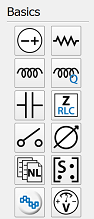
The workspace window of the schematic editor contains components and transmission lines for use when adding schematic elements to a project. Once added to the current schematic, users can edit a component's properties by either double-clicking on the desired component in the schematic window, or right-clicking on the desired component and selecting Edit Properties.
Each component property editor includes element-specific settings, as well as the following general options:
- Name: user-defined component identifier.
 : accesses the analysis definitions editor.
- Label Position: placement of a component's label.
 : determines which information is visible in a component's label.
 - Enabled State: sets a component as either active or inactive. Inactive components are either open or short.
Voltage Source
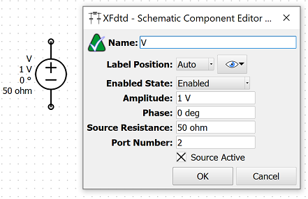
The  button adds an independent AC voltage source to the current schematic.
The following settings define its parameters:
- Amplitude: the AC amplitude of the voltage source. When set to zero, the voltage source acts as a passive resistor with resistance equal to the source resistance.
- Phase: the AC phase of the voltage source.
- Source Resistance: the source resistance of the voltage source. For S-parameter analysis, this value is also used as the port's characteristic impedance. The source resistance must be greater than zero.
- Port Number: a user-defined port number for labeling results.
- Source Active: indicates an active or inactive source. When inactive, the source is treated as a resistor.
Users should note that the frequency of the AC voltage source is set equal to the current sample frequency of the frequency sweep, such that the same amplitude and phase are applied at all frequencies, meaning the source is not frequency dependent. Each voltage source is automatically treated as a port when calculating S-parameters.
Resistor
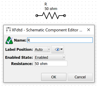
The  button adds an ideal resistor to the current schematic.
The Resistance parameter is the resistance of the ideal resistor, and must be greater than or equal to zero. When set to zero, a minimal resistance is used by the solver.