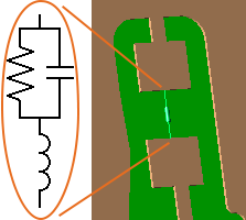
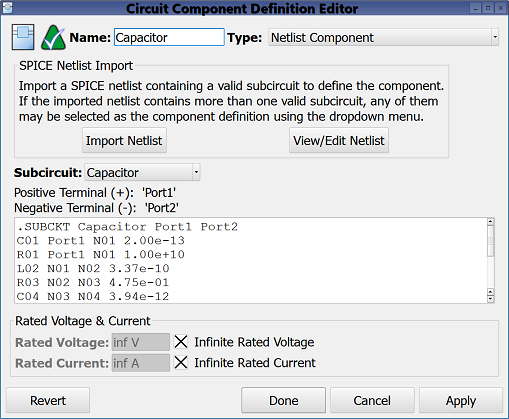
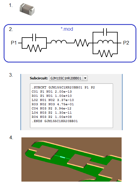
The ![]() Netlist Component definition allows passive SPICE3 circuits to be considered a circuit component definition within the finite-difference time-domain (FDTD) simulation. This co-simulation allows the netlist circuit to be treated as one cell edge, regardless of the actual size and complexity of the circuit being described by the netlist. This allows users to simulate complex circuits without creating the circuit layout piece-by-piece in XF.
Netlist Component definition allows passive SPICE3 circuits to be considered a circuit component definition within the finite-difference time-domain (FDTD) simulation. This co-simulation allows the netlist circuit to be treated as one cell edge, regardless of the actual size and complexity of the circuit being described by the netlist. This allows users to simulate complex circuits without creating the circuit layout piece-by-piece in XF.
Diodes should be included in the netlist component when only time-domain results are of interest. This is because diodes violate the assumptions of linear system theory, making it incorrect to apply either a Fourier or discrete Fourier transform to the time-domain results. A simulation containing a diode produces invalid frequency-domain results—including impedances, S-parameters, and steady-state far-zone fields—even if the time-domain results eventually decay to zero. The time-domain results are unaffected, and therefore are valid.
Additionally, netlist components may be used to define a matching circuit embedded within a feed. The netlist must first be imported, creating a netlist component definition that can then be assigned as a matching circuit in the feed editor.
Controls
Supported Elements and Models
XF supports a subset of the circuit elements and element models available in SPICE, but supports none of the SPICE analysis or output commands.
The following circuit elements are supported:
- Resistors
- Capacitors
- Inductors
- Coupled Inductors
- Subcircuits (used to call another .SUBCKT definition)
- Diodes
The import process will fail if unsupported circuit elements are encountered anywhere in the netlist file. Analysis commands (.AC, .DISTO, .NOISE, etc.) and output commands (.SAVE, .PLOT, .PRINT, .FOUR) contained in a netlist file are ignored during the import process and excluded from the imported data. It follows that XF supports only .MODEL definitions corresponding to currently supported element types.
After a netlist file is imported, only valid subcircuit definitions from the netlist may be used as the netlist component definition. If the netlist file contains more than one valid subcircuit, the desired subcircuit may be selected from the drop-down menu in the editor.
The following rules define a valid .SUBCKT definition:
- It must only contain the supported circuit elements described above.
- It must have two, three, or four external nodes/terminals. Three and four terminal subcircuits may only be used to define a matching circuit, and cannot be used to define a standalone circuit component.
- It must not be nested inside another subcircuit definition.
Conventions and Syntax
Detailed information about how SPICE3 netlists are structured and written can be found at the University of California at Berkeley's EECS Department.
There are a few key differences between the official SPICE3 conventions and syntax and what XF supports for imported netlist files:
- Model parameters should be listed and separated by spaces, following the model type on a .MODEL definition line rather than appearing inside parenthesis following the model type. For example, .MODEL Model-Name ModelType Param1=Value1 Param2=Value2...
- Only .SUBCKT definitions may be used as the netlist component definition. The top-level netlist circuit described by elements that are defined outside of a .SUBCKT definition will be unavailable to use as the netlist component definition. To use those elements, users must group them into their own .SUBCKT definition in the netlist file prior to import.
- Model, subcircuit, and element names may contain underscores (_) only when they are in addition to alphanumeric characters, and must begin with a letter.
- Subcircuit and element terminal names must contain only underscores and alphanumeric characters, and are not required to begin with a letter.


