The  Huygens Surface Sensor records both steady-state electric and magnetic fields near the boundary of the FDTD simulation space. Users can export these fields for use in Wireless InSite, a ray-tracing simulator, where they represent an antenna's radiation characteristics. Steady-state frequencies are specified when creating the FDTD simulation.
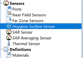
Users can open the Huygens surface sensor editor by double-clicking on Huygens Surface Sensor in the Project Tree. In the Huygens Surface Sensor tab, checking the Enable Huygens Surface Sensor option enables the sensor as well as two tabs with additional settings.
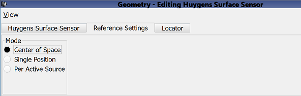
The Reference Settings tab allows users to specify a reference point for single- and multi-port devices. The reference point has no bearing on the FDTD simulation, however, when exported to Wireless InSite it defines the source or termination location of ray paths.
Users can select one of three different Mode options. Center of Space is XF's default setting that determines the reference point based on the bounding box of the grid. This location may change between simulations if the grid's size changes due to parameterized geometry or other settings.
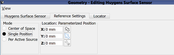
Single Position specifies a constant location for use as the reference point. Users can either enter values into the X, Y, and Z fields, or use the three adjacent picking-tool buttons in order to select a point based on geometry.
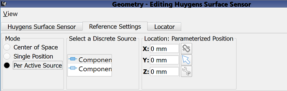
Per Active Source sets a unique reference point per feed in a project containing multiple feeds. When using this mode, XF expects only one active feed per Simulation : Run—as is the case when S-parameters are requested.
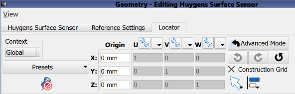
Under the Locator tab, users can define a geometry reference coordinate system. This coordinate system has no bearing on the FDTD simulation, however, when exported for use in Wireless InSite it places the antenna in the propagation environment.
The editor provides multiple options for defining both the origin and orientation of the U', V', W' vectors, and the advanced settings, direction picking tools, and alignment tools provide additional methods for making adjustments.
Four buttons provide options for completing changes to the editor:
- Revert: discards changes and restores the previously saved settings.
- Done: closes the window and saves the entered specifications, which are visible when the window is re-opened.
- Cancel: closes the window and does not save the entered specifications.
- Apply: saves the entered specifications but does not close the window.