The  Surface Current Sensor computes the electrical current on a metal surface, as expressed in the following equation:
where $H$ is the magnetic field tangent to the outside of the metal surface. Users can view the output on parts either with or without XACT mesh enabled, and use this analysis to understand how a complex antenna works and identify the appropriate modifications to improve it.
A surface current sensor is always paired with a surface current sensor definition. The former specifies from where the data is collected, and the latter defines which data will be collected and when.
Use Case
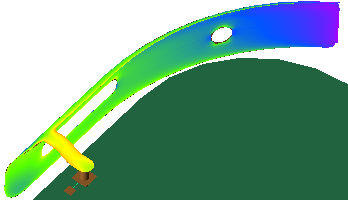
The surface current sensor is primarily used for building antennas that perform well at multiple frequencies. Users can view the surface current on only the antenna rather than the entire complex circuit in order to more easily identify issues and make the appropriate changes.
The sensor can collect data on any part when the following conditions are met:
- Parts must be good electrical conductors.
- XACT and staircased parts are both supported.
Controls
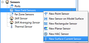
Users can create a surface current sensor by right-clicking on Sensors in the Project Tree, then selecting New Surface Current Sensor. The editor across the top of the Geometry window consists of three tabs: Properties, Parts, and Bounding Box.
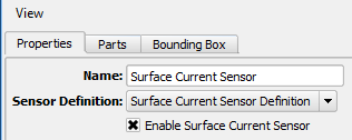
Under the Properties tab, users can enter a Name and specify the associated Sensor Definition by choosing from the current project's existing sensor definitions listed in the drop-down menu. The default selection is the Surface Current Sensor Definition added to the Definitions branch of the Project Tree once the sensor is created.
The Enable Surface Current Sensor option can be checked to include the sensor's data in a simulation. If the option is unchecked, data is not collected during the simulation, but the sensor remains in the project for later use.
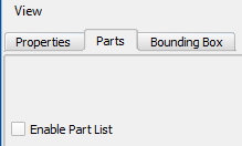
Under the Parts tab, Enable Part List allows users to select a specific set of parts to collect data from. If the option is unchecked, data will be collected from all parts that are conductors.
There are two methods for selecting parts:
- Click within the Geometry window to select a part, and hold Ctrl to select multiple parts.
- Click in the Project Tree to select a part and hold Ctrl to select non-consecutive items, or hold Shift to select a range of parts.
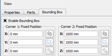
Under the Bounding Box tab, Enable Bounding Box allows users to reduce the spatial limits of data collection to the specified volume. If the option is unchecked, data will be collected within the bounding box of the grid.
The sensor will collect data where the part and bounding box overlap. If the selected part is partially within the bounding box, then the sensor will collect data only on the portion of the part's surface that is within the bounding box. When the bounding box and part list are both enabled and the selected part is not within the bounding box, the sensor will not collect data.