
XF's post-processing option allows users to make use of the electromagnetic principle of superposition in order to combine steady-state results from a single FDTD simulation that computed S-parameters for multiple ports and included a far zone sensor. Array optimization determines the set of port phases that maximize an array's EIRP in specified directions. See the antenna array use cases knowledge article for prerequisites and use cases.
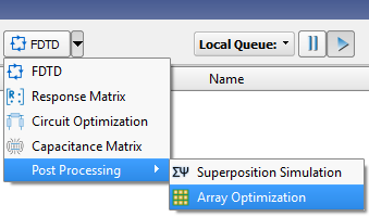
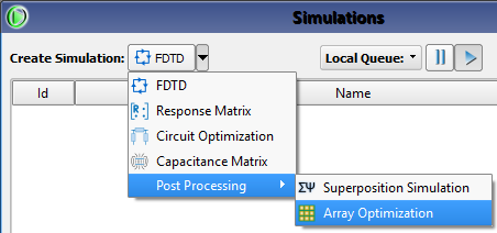
Users can create an array optimization through the Simulations window by using the Create Simulation drop-down arrow to choose Post Processing ❯ Array Optimization.
In the Create Array Optimization window that opens, the Name field at the top of the window provides space for a user-defined identifier. This name appears in the Simulations window once the simulation is created, and is editable from that window through the right-click menu.
Input Simulation Tab

The Input Simulation tab allows users to choose the source of the steady-state results for post-processing.
Input Project drop-down menu lists projects that are loaded in the current project's Results browser. This selection determines which input simulations are available.
Input Simulation drop-down menu lists simulations that belong to the selected input project. This selection determines the steady-state results available for optimization.
A summary of the input simulation is displayed in the window below the input settings.
Array Definitions Tab

The Array Definitions tab allows users to create arrays by grouping ports. The Name column provides an identifier for each array and the Summary column lists the combination of ports, phases, and type of power specified for the associated array.
Two buttons above the array table control its contents:
- The
button adds an array to the optimization.
- The
button removes the selected arrays from the optimization.
Add an Array

Clicking the button in the Array Definitions tab opens the Array Definition Editor window containing three tabs with options for creating an array.
The Name field at the top of the window provides space for a user-defined identifier. This name appears in the Array Definitions tab once it is added to the optimization.
In the Ports tab, two buttons provide options for choosing components:
- Select All: includes all available components in the array.
- Deselect All: excludes all available components from the array.
Users can also include or exclude an individual component by selecting or deselecting its associated checkbox, respectively.
The Available Power Specification setting determines how power is distributed to the ports.
- Total: divides the available power evenly among all ports.
- Per Port: delivers a different power to each port.
The Total Available Power field is editable when Total is selected as the Available Power Specification setting. This user-defined value defines the amount of power distributed evenly among all ports.
The Available Power for Port option is enabled when Per Port is selected as the Available Power Specification setting. Its drop-down menu lists each component selected in the tab's window, and the editable field allows users to enter a different power for each component selected from the associated drop-down menu.

The Allowable Phases tab settings define the set of phase values applied to each port. The optimization algorithm determines the optimal phases based on this larger set.
- Minimum Allowed Phase: the smallest phase allowed for each element.
- Phase Step: the increment that determines the space separating each phase value between the minimum and maximum phases.
- Maximum Allowed Phase: the largest phase allowed for each element.

The Notes tab provides space for users to attach memos to the array, such as a brief description of its specifications for later reference. Once the array is created, these optional notes appear in the notes tab of the simulations window.
Clicking the OK button adds the array to the optimization. Clicking the Cancel button closes the Array Definition Editor window without adding the array to the optimization.
Analysis Definitions Tab

The Analysis Definitions tab allows users to set goal functions for the optimization and apply a different analysis to each array. The Analysis Type column indicates that a Max EIRP Analysis is performed at the specified angles, the Name column provides an identifier for each analysis, and the Array column displays the name of the selected array.
Two buttons above the analyses table control its contents:
- The
button adds an analysis to the optimization.
- The
button removes the selected analyses from the optimization.
Add an Analysis

Clicking the button in the Analysis Definitions tab opens the Analysis Definition Editor that allows users to create an analysis and specify the beam angles at which to perform the optimization.
The Name field at the top of the Analysis Definition Editor provides space for a user-defined analysis identifier. This name appears in the Analysis Definitions tab once it is added to the array.
The Array Definition drop-down menu lists the arrays previously defined in the Array Definitions tab.
The Far Zone Sensor drop-down menu lists each sensor associated with the input simulation, and allows users to choose which sensor to use for the max EIRP analysis. The optimization determines a set of port phases that maximizes EIRP for each row in the table.
The Specify Beam Angles table contains two columns that display the user-defined Theta and Phi angles for each analysis.
Four buttons above the table control its contents:
- The
button adds a new beam angle or a saved beam angle list from its drop-down menu.
- The
button replaces all of the beam angles with a saved beam angle list from its drop-down menu.
- The
button removes the selected beam angles from the analysis.
- The Delete All button removes all beam angles from the analysis.
The Optimization Settings include two options for optimizing the values of the specified beam angles. Users can set different optimization parameters for each analysis to accomodate various requirements.
When checked, the Use Default setting aplies default values to the analysis, which is fine for most applications. Unchecking this option enables the Edit Optimization Settings button.
The Edit Optimization Settings option allows users to set the parameters that control the optimization.

A particle swarm optimization algorithm is used to select port phase values and users can adjust how the optimization searches the solution space by clicking the Edit Optimization Settings button to open the Array Optimization Analysis Optimization Settings window. Users can enter the desired values, as well as utilize the two checkbox options at the bottom of the window. Mousing over these options displays a tooltip with additional information.
CVT, or Pseudo Centroidal Voronoi Tessellation, is an initialization method that attempts to evenly distribute the starting population within the search space. When checked, the CVT option can reduce the variance of results and increase the effectiveness of the search at the cost of longer initialization times.
Human Behavior is a particle behavior strategy that, when checked, includes negative feedback from the population's worst performers, as well as the standard behavior of the population's best performers.
Clicking OK closes the Array Optimization Analysis Optimization Settings window and saves the optimization settings. Clicking Cancel closes the Array Optimization Analysis Optimization Settings window without saving the optimization settings.
Clicking the OK button adds the analysis to the array. Clicking the Cancel button closes the Array Optimization Analysis Editor without adding the analysis to the array.
Notes Tab

The Notes tab provides space for users to attach memos to the optimization, such as a brief description of its specifications for later reference. Once the optimization is created, these optional notes appear in the notes tab of the simulations window, and are editable in that window by right-clicking on the desired optimization and selecting from the menu.
Create and Queue

Four buttons provide options for completing the optimization setup:
- Create & Queue Optimization: writes the input files to disk and queues the optimization to run.
- Create Optimization Only: writes the input files to disk but does not queue the optimization.
- Done: closes the Create Array Optimization window and saves the entered specifications, which are visible when the window is re-opened.
- Cancel: closes the Create Array Optimization window but does not save the entered specifications.
The Create Array Optimization window closes once users make the final selection, and created optimizations appear in the Simulations window.