Antenna group delay is the transit time of a signal that is input at the antenna's feed location to propagate through the matching network, radiating element, and device packaging into free space. The transit time is frequency dependent, causing variations in the propagation speed versus frequency to distort the signal. An increase in channel bandwidths, such as in ultra-wideband (UWB) applications, highlights the significance of antenna group delay as a design metric that impacts data rates in communication systems.
Definitions
Group delay, $\tau$, is the rate of change in the device's phase response with respect to frequency [1].
\begin{equation} \tau(f) = -\frac{d\psi}{d\omega} \end{equation}where $\psi$ is the device's phase response, $\omega=2\pi f$ is the radial frequency, and $f$ covers the device's operating frequency range.
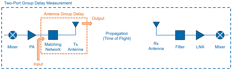
In a laboratory setting, a two-port group delay measurement is taken using a vector network analyzer (VNA). Typically, two identical antennas are separated by a minimum of the far-field distance, and aligned such that the transmitter (TX) and receiver (RX) have both the same polarizations and look directions.
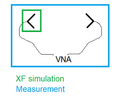
Determining antenna group delay from a two-port measurement is challenging because the measured quantity is a function of the TX antenna, the RX antenna, and the separation distance. In order to determine the group delay associated with a single antenna—either TX or RX—some analysis of the measured two-port group delay must be performed. In XF, antenna group delay is determined directly from a single-antenna simulation.
Please log in to view this content.
Remcom customers and those interested in our products may access this content after logging in.
Interpretation
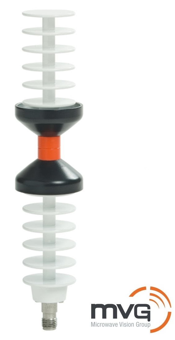
Consider an MVG WD6000 aligned with the z-axis. Over a frequency range of 6 GHz to 10 GHz, the antenna's input impedance and stable far-field radiation patterns make it an excellent UWB antenna.
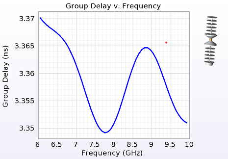
$\tau(f)$ is computed at a single observation point, (90°, 0°). It has a maximum value of 3.370 ns, minimum of 3.349 ns, $\delta$ of 21 ps, and an approximate DC offset of 3.36 ns. The DC offset is inconsequential because it either increases or decreases depending on the time-of-flight to the receiver and has no bearing on distortion. $\delta$, however, indicates how much distortion the antenna introduces into the communications system and is the primary metric of interest.
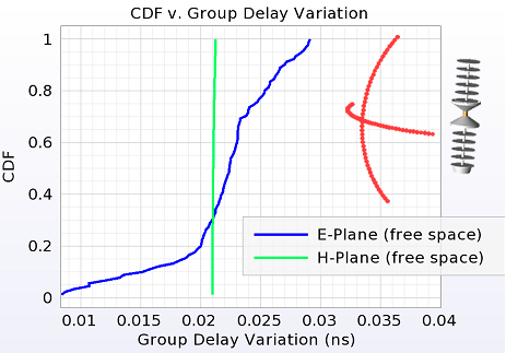
The antenna radiates in all directions and $\delta$ is computed for each. Multiple observation points along the antenna's E- and H-planes are specified and the CDF of $\delta$ is computed for each set. As expected, the H-plane shows a near-vertical line due to the antenna's rotational symmetry, and the E-plane shows more variation due to the pattern roll-off from the boresight.
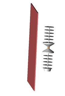
Antennas rarely operate in ideal free space conditions. Instead, they are packaged in a device with plastic housing, a battery, and other objects that degrade their performace. By introducing a thin sheet of dielectric material near the antenna, users can analyze its impact on group delay. As an example, this sheet has dimensions of 2 mm x 200 mm x 200 mm, is separated from the antenna by 39 mm, and is a lossless dielectric with a $\epsilon_r$ of 4.
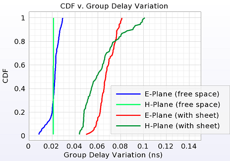
The CDF of $\delta$ shows the group delay moving to the right for both the E- and H-planes. The H-plane is no longer a vertical line because the transmissions through and diffractions around the sheet break the rotational symmetry. The worst-case $\delta$ value approaches 100 ps.