The finite-difference time-domain (FDTD) method calculates electromagnetic fields within the near-field of a simulated structure. Enlarging the simulation space to include the structure's far-field region is computationally demanding and not practical for most analyses, such as those performed with radar scattering or antenna radiation. The most efficient method to compute far-zone results is a mathematical transform that produces far-field values based on near-field data.
In XF, the process is referred to as the near- to far-field transform (NTFF). Here, near-field electric and magnetic fields that are tangential to a closed surface containing the simulated structure are integrated to arrive at the far-field response. It utilizes the surface equivalence theorem, which states that fields outside a closed fictitious surface are calculated by placing nonphysical current densities on the surface such that the fields inside the closed surface are zero and those outside are equal to the fields radiated by the structure inside the surface [1].
XF computes far-field results using a three-step process:
- Compute near-field values during FDTD simulation.
- Compute electric and magnetic current densities on the far-zone box.
- Perform near- to far-field transform.
References
- Balanis, Constantine A., Advanced Engineering Electromagnetics, John Wiley & Sons, 1999.
Near-Field Computation
Far-Zone Box Representation

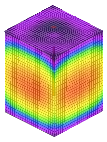
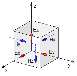
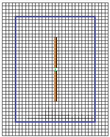
The tangential $E$ and $H$ fields on the far-zone box are visualized by placing planar sensors at the location of the far-zone box. Crossing the far-zone box, the fields radiated from the dipole reach the end of the simulation space where they are absorbed by the outer boundary conditions.
Applying the surface equivalence principle, the sources $J_1$ and $M_1$ at the dipole are replaced with nonphysical electric and magnetic currents flowing tangentially along the far-zone box given by the following equations:
\begin{equation} J_s = \hat n \times (H_1 - H_0) \end{equation} \begin{equation} M_s = - \hat n \times (E_1 - E_0) \end{equation}where,
$E_0 $ = electric field one cell inside the far-zone box
$H_0 $ = magnetic field one cell inside the far-zone box
$E_1 $ = electric field one cell outside the far-zone box
$H_1 $ = magnetic field one cell outside the far-zone box
$\hat n $ = unit outward normal vector to the far-zone box
The virtual electric and magnetic currents $J_s$ and $M_s$, respectively, radiate both inside and outside the far-zone box, and serve as the sources for the far-field values. In order to compute the far-field values, the $E_0$ and $H_0$ fields are set to zero.
The resulting equations compute the current densities on each cell of the far-zone box:
\begin{equation} J_s = \hat n \times H_1 \end{equation} \begin{equation} M_s = - \hat n \times E_1 \end{equation}Near- to Far-Field Transform
The surface currents $J_s$ and $M_s$ at every cell edge on the far-zone box are integrated to arrive at the far-field results for a single observation angle, defined by a $\theta$ and $\phi$ direction.

