A ![]() Feed
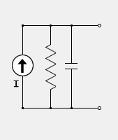
circuit component definition is an active component that allows users to specify a voltage or current source. It consists of RLC components and an input waveform that modifies the electric field on its cell edge.
Feed
circuit component definition is an active component that allows users to specify a voltage or current source. It consists of RLC components and an input waveform that modifies the electric field on its cell edge.
Controls

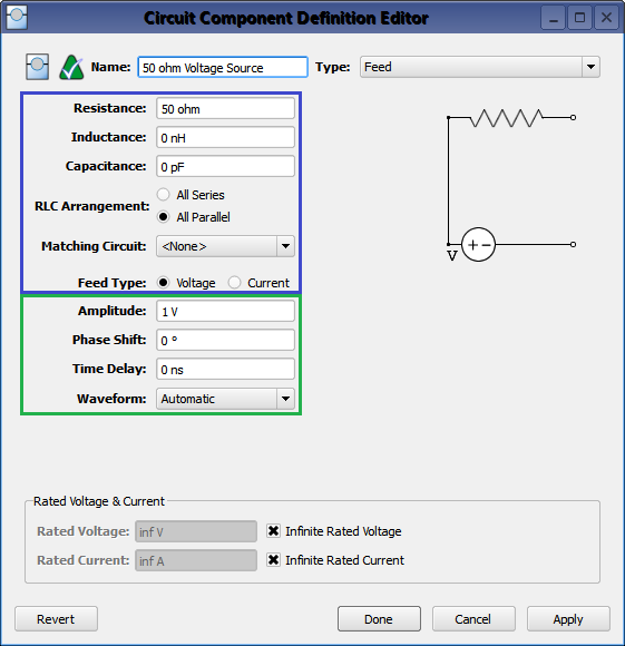
Double-clicking on a circuit component definition in the Definitions branch of the Project Tree opens the Circuit Component Definition Editor, where a feed is created by choosing Feed from the Type drop-down menu. The top group of controls define the layout of the RLC components with the source.
- Resistance: source resistor.
- Inductance: source inductor.
- Capacitance: source capacitor.
- RLC Arrangement: determines whether the RLC components are treated in parallel or in series. The series and parallel options affect only the configuration of the RLC elements and not their relation to the source. As such, the RLC components are always in series with a voltage source or in parallel with a current source.
- Matching Circuit: specifies which netlist component is used as the feed's matching network.
- Feed Type: chooses between a voltage and current source.
Specifying a two port matching circuit enables a Matching Circuit Arrangement option that allows users to decide whether the network is in series with or parallel to the source resistor. Additionally, the source inductor and capacitor must be zero when a matching network is specified.
The bottom group of controls defines the waveform and how it is applied to the simulation space.
- Amplitude: the peak, not RMS, value of the input waveform used to compute available power.
- Phase Shift: applied to the associated waveform, but only if the waveform is a sinusoid.
- Time Delay: applied to the associated waveform, but only if the waveform is not a sinusoid.
- Waveform: associated waveform definition applied to the source.
Users should note that either Phase Shift or Time Delay will be applied depending on whether or not the waveform is a sinusoid.
Rated Voltage & Current settings apply to electrostatic discharge (ESD) analysis. Both Rated Voltage and Rated Current default to infinity, but users can change either value by unchecking the associated box and entering the desired value or expression. These settings do not affect energy propagation through the component, but XF checks the voltage and current at each timestep during a simulation to see if they exceed the rated values. Users can adjust these settings to flag components that are likely to experience damage or failure during a simulation.
Pi Matching Network Example

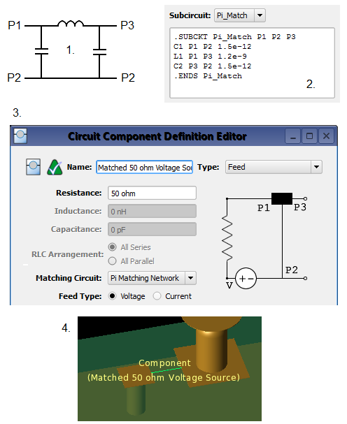
Consider a Pi matching network for a simple antenna. Rather than creating three circuit components and laying them out in XF's geometry window, the matching network can be defined in the feed definition using a netlist component by following these steps:
- Determine the schematic layout and component values of the matching network.
- Define the matching network in XF as a netlist component.
- Select the netlist component in the feed definition editor.
- Place the matched feed on a single cell edge in the finite-difference time-domain (FDTD) simulation space as a Circuit Component.

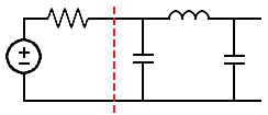
This matching network has three external ports that plug into the feed. Simulated results are defined in the following ways:
- Available power, $P_{av}$, is determined based on the values of the amplitude and source resistance. It is the power available on the left side of the dashed red line.
- Input power, $P_{in}$, measures the amount of power transferred to the matching network. It is the power passing left to right across the dashed red line.
- Reflection coefficient, $\Gamma$, is measured between the source resistor and port 1 of the matching network. It is the reflection at the dashed red line.
- Matching circuit loss, $P_{mcl}$, is the power lost in the matching network. It is the power lost in the components to the right side of the dashed red line.
