The  Solid Sensor Definition allows users to specify both time-domain and frequency-domain fields in order to collect data by capturing mesh-snapped fields within a volumetric space. A definition must accompany a solid sensor in order to collect data at the location of a specific vertex.
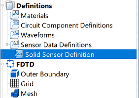
Users can access the Solid Sensor Definition Editor by either right-clicking on the Definitions branch of the Project Tree and selecting New Solid Sensor Definition, or double-clicking on an existing definition in the Project Tree.

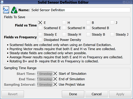
The Fields to Save options determine which output to save by allowing users to select one or more of the following Field vs Time options:
- E: electric field versus time.
- H: magnetic field versus time.
- B: magnetic flux versus time.
- J: current density versus time.
- Scattered E: scattered electric field versus time.
- Scattered H: scattered magnetic field versus time.
- Scattered B: scattered magnetic flux versus time.
Users should note that the scattered fields are collected only when using a plane wave excitation and the scattered-field formulation is specified when creating a finite-difference time-domain (FDTD) simulation. Poynting vector is an available result when both E and H versus time are collected.
Users can also choose one or more of the following Fields vs Frequency options:
- Steady E: electric field at one or more discrete frequencies.
- Steady H: magnetic field at one or more discrete frequencies.
- Steady B: magnetic flux at one or more discrete frequencies.
- Steady J: current density at one or more discrete frequencies.
- Dissipated Power Density: volumetric dissipated power density at one or more discrete frequencies.
Users should note that steady-state fields are collected only when frequencies of interest are specified when creating an finite-difference time-domain (FDTD) simulation. Average power results require that both E and H versus frequency are collected, and rotating B+ and B- require that B versus frequency is collected.
The Sampling Time Range settings specify when cell edge data is saved to disk and made available for graphing. Users can either enter the desired Start Time and End Time, or check Start of Simulation and End of Simulation to assign the sampling time range to the simulation's beginning and ending values, respectively. Users can either enter a value for the Sampling Interval, which determines how often data is sampled within the time range, or check the Use Project Value option to define the Sampling Interval using the value in the advanced tab of the project properties editor. By default, XF selects a sampling rate that prevents aliasing of frequency-domain output.
Four buttons provide options for completing changes to the project properties:
- Revert: discards changes and restores the previously saved settings.
- Done: closes the window and saves the entered specifications, which are visible when the window is re-opened.
- Cancel: closes the window and does not save the entered specifications.
- Apply: saves the entered specifications but does not close the window.
![]() Solid Sensor Definition allows users to specify both time-domain and frequency-domain fields in order to collect data by capturing mesh-snapped fields within a volumetric space. A definition must accompany a solid sensor in order to collect data at the location of a specific vertex.
Solid Sensor Definition allows users to specify both time-domain and frequency-domain fields in order to collect data by capturing mesh-snapped fields within a volumetric space. A definition must accompany a solid sensor in order to collect data at the location of a specific vertex.
