The outer four edges of a waveguide interface are treated as a perfect conductor by the eigensolver. Users should specify perfect electric conductors (PEC) and/or perfect magnetic conductors (PMC) depending on the waveguide structure or transmission line being fed.
Background
The outer edges of a waveguide interface require the application of a boundary condition, similar to the full finite-difference time-domain (FDTD) space. Boundary conditions for waveguides are limited to PEC and PMC, and the appropriate choice depends on the orientation of the electromagnetic fields adjacent to each given boundary and the material properties it intersects. When dielectric and free space materials are coincident with an edge, PEC is preferred for electric fields that are primarily normal to the boundary, and PMC is preferred for those that are tangential. Edges coincident with ground or another conductor are typically set to PEC because the field values are close to zero.
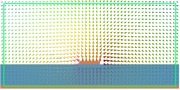
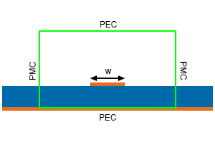
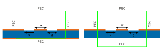
For example, the image shows the typical quasi-TEM E-field distribution for a microstrip along with the four edges of the waveguide interface drawn in green. The E-field along the vertical sides is strongest just above the air-dielectric boundary. At this point, E is mostly tangential to the vertical sides and H (not shown) is mostly normal to them. The vertical boundaries should be set to PMC because it best satisfies this condition. The strongest E along the top horizontal boundary is directly over the microstrip and is mostly normal to the top boundary at this point (H tangential). The upper boundary should be set to PEC because it best satisfies this condition. The lower horizontal boundary is in the conducting ground plane and will have near-zero fields so that boundary type is of little importance. In this case, the boundary would typically be set to PEC.
Controls
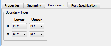
The Boundaries tab of the new waveguide interface editor provides four drop-down menus corresponding to the four edges of the interface, which are determined by the U, V coordinates under the Geometry tab. Each drop-down menu allows users to select either PEC or PMC.
Recommendations
PEC should be chosen for classic rectangular or circular waveguide structures with conducting material on all sides because it matches the material properties of the waveguide.
The following are recommended choices for common transmission lines:
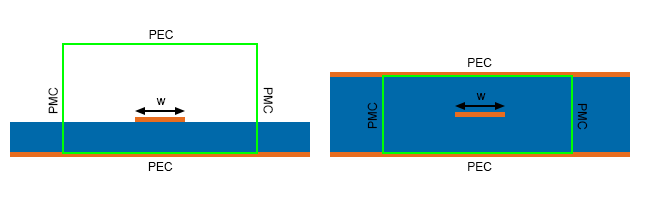
For structures with uncertain field distributions, set the waveguide geometry larger then necessary and run the eigensolver under the port specification tab. View the fields for a node or mode to determine where E-fields are tangential and normal.
Running a few simulations can determine the impact of a boundary conductor on simulated results. Keeping everything fixed in the project, users should select different sets of boundaries, run a simulation for each, and compare the results to determine their sensitivity to the boundary conductor.