The main grid editor sets the base cell size and extents of the simulation space and provides the default values for any part with PrOGrid grid regions enabled. Users can specify fixed points and grid regions, as well as view information about the grid. For reference, the gridding algorithm page explains how the main grid fits into the overall gridding framework.
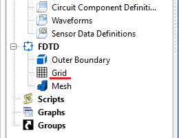
Users can access the Editing Grid editor by either double-clicking on the Grid node in the FDTD branch of the Project Tree, or using the drop-down arrow in the upper-left corner of the Geometry window to select Grid Tools, and then clicking the Edit Grid button.
The gridding specifications influence the simulation's memory requirement, so an estimate is always visible on the right side of the editor. The Current bar displays the amount of memory required to run a simulation in the project's current state. The New bar displays the amount of memory required to run a simulation based on unsaved changes in the editor's six tabs.
Four buttons appear in the upper-right corner:
- Revert: discards changes and restores the editor's settings to the previous saved version.
- Done: closes the editor and saves the entered specifications, which are visible when the editor is re-opened.
- Cancel: closes the editor but does not save the entered specifications.
- Apply: leaves the editor open and saves the entered specifications, which are visible when the editor is re-opened.
When changes are made in the grid editor, the mesh view controls open across the bottom of the geometry window allowing users to visualize the grid.