October 26, 2016: The content below helps navigate the new features in this release. A full list of updates is available in the Reference Manual's Appendix.
XFdtd 7.6.0 is the last XF release series available for 32-bit Windows and RedHat Enterprise Linux (RHEL) 5 platforms. Subsequent releases will be available for 64-bit Windows and RHEL7, and additionally for RHEL6 for the solver. RPS subscribers will receive additional notice of this change.
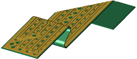
Wrap Flexible PCB and Sheets
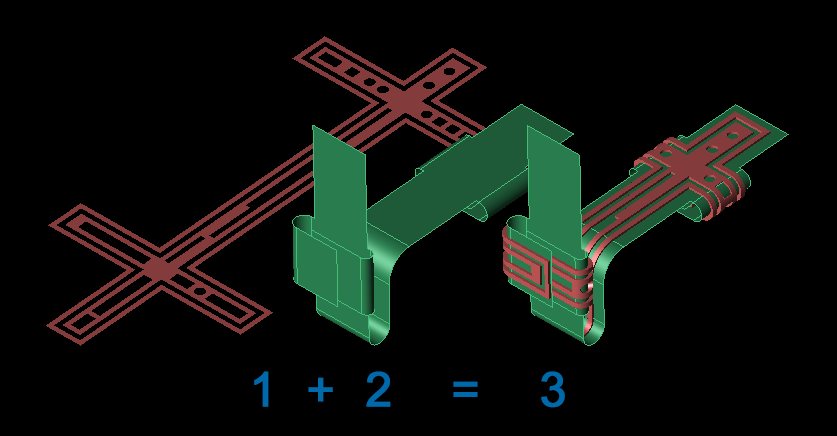
This release introduces wrapping capabilities that conform a flat design to an arbitrary surface. This ability supports a full, multi-layer flexible PCB during import so users do not need to wrap each layer manually—they simply select the PCB option from the import menu, provide the form, and let XF do the work.
Also included in this release is a Wrap Sheet feature for single-layer design, such as conformal antennas. Rather than performing a series of bends, users can easily apply geometry to the desired shape without knowing its parameters for a simplified modeling process.
Create Movies of Output
 XF's animated field output sequences can be saved as movies directly through the user interface. This enables users to embed movies in PowerPoint slides or present output on different computers without installing XF on that machine. Users can change their focus to a different application or use a remote desktop when creating movies, which are rendered in the sequence's predetermined framerate.
Dielectric Volume Averaging
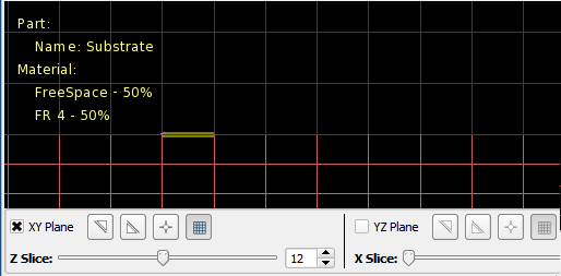 XF's latest meshing feature averages material parameters for simulations with high permittivity materials, such as a ceramic chip antenna. When dielectric volume averaging is enabled, XF adds an averaging layer on the surface of dielectric materials for increased accuracy. Users should enable this meshing feature for thick parts that are at least three cells across, but not for thin parts with only one cell thickness.
Far Zone Phase Reference Point
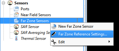 XF users can define the phase reference point used in far zone computations. This affects electric field phase output, which is important for antenna array design. In addition to XF's default center of space setting, the phase reference point selections include single position and per active source. Exported UAN files reflect this update by containing the additional attribute reference point, which is measured in global space in meters.
Rectangle Select Tool
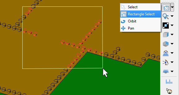 XF's latest selection tool allows users to choose numerous parts simultaneously. By quickly grabbing portions of either the drawing area or parts list, users avoid selecting each object individually.
On-Screen Display
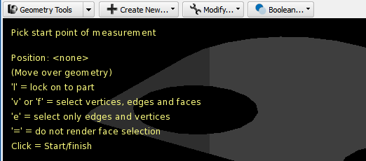 Information previously displayed in XF's status bar has been moved on-screen for greater visibility. The cursor's coordinates appear in bold text within the geometry window, as well as instructions with modifiers that guide users through the 2-D sketcher and picker tools' functionality. Tooltips and mesh information also appear on-screen for more accessible options.
Edit Simulation Name and Info
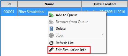 This usability update allows users to edit the simulation name and notes after the simulation has been created. This is useful for adding supplementary comments based on computed results or changing the name to something more meaningful.
General RLC Option for CEO
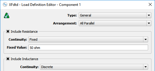 XF's latest addition to the circuit element optimizer's (CEO's) capability includes a generalized component for greater flexibility and a simpler circuit modeling process. The general RLC option allows users to define equivalent circuits as RLC, R||L||C, and RL||C in order to accurately represent complex behavior in fewer steps.
Additional Capabilities
This version introduces over 70 usability, performance, scripting, and other updatesHere is a select list of modifications:
- Collaborated with Nebens enabled users to export directly from XF to MIMObit format.
- Added ability to import a Bill of Materials (Bom) from Granta Design's MI:Materials Gateway along with a CAD model.
- Added ability to import an Xpatch .facet file.
- Added ability to import and export parameters in the parameter list.
- Expanded project unit preference options to display efficiency values as percentage, fraction, or dB.
- Added test to determine whether the meshed representations of two objects touch each other. Users can select two objects, right-click, choose Touching Objects, and then Test Objects in Mesh Space. Note that this is not a conductivity continuity test.
- Tested for compliance and simulations run in accordance with the specific absorption rate (SAR) specification in IEC/IEEE 62704-1 Draft 4.
- Improved simulations containing multiple frequencies of interest with use of multiple threads for the discrete Fourier transform (DFT) computation. This results in substantial performance increases in some cases.
- Reduced plotting times of far zone gain results when multiple active feeds are present.
- Improved performance for the separate modeling operation.
- Improved creation of a sheet body from faces by displaying the number of selected faces.
- Specified additional XFsolver command-line options as External Queue Integration (EQI) options.
- Eliminated multiple computations for duplicate frequencies of interest during a simulation.
- Added an application preferences option that displays the process ID in the title bar of all windows belonging to a single instance of the application. This is useful for disambiguating pop-up dialogs.
- Updated the grid editor's info tab to display the total number of cells in the user space and the total number including any PML layers.
- Added ability to specify the CAD import options before the import begins if modeling units of an imported CAD design are known.
- Added ability to toggle port settings on a selection of multiple enabled circuit components.
- Included the net input power along with the other SAR sensor data displayed in the SAR statistics window.
- Updated the default setting to draw the CEO's S-parameter and efficiency result plots with lines instead of markers.
- Added option to application preferences that does not display lumped component name in the view when selected.
- Added dissipated power per material sorting option to the system sensor table.
- Fixed bug causing the include in mesh option on a circuit component to not update the grid. This includes changes to the grid bounds for circuit components included in the padding calculation's bounding box, fixed points for components with fixed points enabled, or grid regions for components with PrOGrid grid regions enabled.
- Reduced time and RAM necessary to create a sheet body from many faces.
- Removed the ineffectual minimum cell size option from the main grid editor.
- [Scripting API] Added App.getResultBrowserSelection() to obtain the current selection in the results browser.
- [Scripting API] Added CachingOperation, which can be used to increase performance of querying data set values.
- [Scripting API] Added methods to Waveguide to be able to query and set the Boundary Type