This example demonstrates XF's workflow for evaluating a diplex matched antenna and analyzing two different matching network states simultaneously.
The antenna in this workflow example is a dual-band antenna designed for the GPS L1 band and the 2.4 GHz WiFi band containing channels 1 - 14. First, the characteristic impedance of the antenna is determined via an FDTD simulation and then a matching network is evaluated to see the matched performance of delivered power.
The steps in the antenna design workflow form the basis for this project, however, this example focuses on the following aspects.
- The geometry includes the ground, antenna, and substrate.
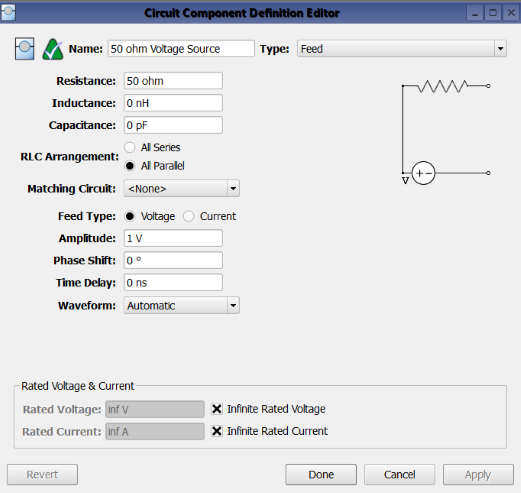
- An unmatched voltage source excites the antenna.
- An FDTD simulation requesting S-parameters for the unmatched port is created.
- In post-processing, a schematic is created for computing the matched S11 and delivered power results.
Geometry

In order to compute the dual-band antenna's performace, all required geometry must be added to the parts list. In this example, that consists of the antenna and ground plane, each created as a sheet body, and a substrate created as a cuboid.
Excitation
Simulation

Prior to running an FDTD simulation, the remaining steps—including material assignment, gridding, and meshing—in the antenna simulation workflow must be completed. Although it requires no additional action, users should note that XF adds a port sensor requesting broadband S-parameters along with the circuit component.
This example applies the following simulation settings:
- Compute S-parameters for the unmatched port.
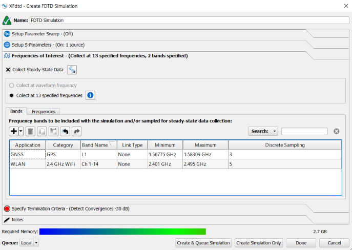
- Specify two frequency bands—the first is GPS L1, and the second is 2.4 GHz WiFi containing channels 1 - 14.
Running an FDTD simulation produces the antenna's unmatched full-wave results.
Post-Process: Schematic

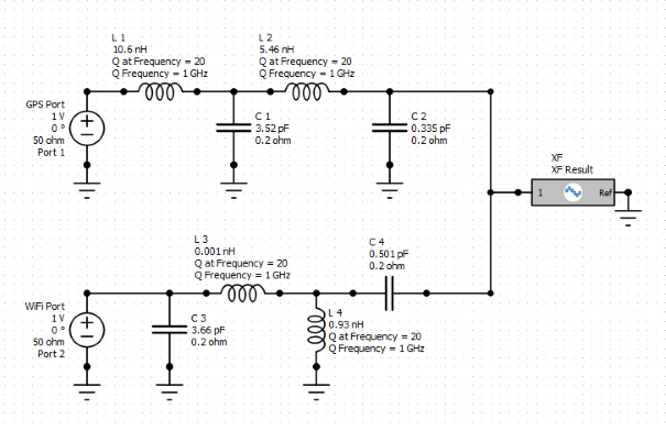
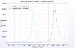
Once the simulation is complete, users can view the unmatched S11 result through XF's results browser. In order to analyze the matched results, a schematic must be created in post-processing. A diplex matching network is built and simulated in the schematic editor to evaluate the antenna's two operating modes.
Please log in to view this content.
Remcom customers and those interested in our products may access this content after logging in.


