A  Far Zone Sensor uses the near- to far-field transform to compute antenna radiation and radar cross section (RCS) patterns at a theoretical infinite distance from the simulation space. It is available either when all six outer boundary conditions are absorbing, or when one PEC boundary and five absorbing are used.
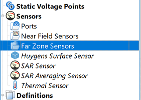
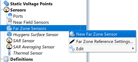
Users can create a far zone sensor by right-clicking on Far Zone Sensors in the Project Tree, then selecting New Far Zone Sensor. The editor across the top of the Geometry window consists of two tabs: Geometry and Properties.
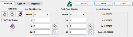
Under the orientation tab, users can define the orientation that will be used to collect far zone data.
To get the most accurate results, a project's geometry should be aligned with the FDTD grid, but sometimes it may already be set up in a different coordinate system. With the orientation tab, users can align the sensor with the device without having to make any changes to the geometry. This doesn't mean that a sensor's orientation has to be attached to geometry; it can be set to whatever rotation makes plotting theta/phi slices or other results easiest for the user's use case.
With the widgets in this tab, users can adjust the primary and secondary directions of the sensor's orientation. The orientation may also be adjusted by right-clicking on an axis and picking an option in the context menu to adjust its direction.
Each far zone sensor has its own orientation, which allows users to have multiple sensors set up with different rotations for different usages. In the project tree, each far zone sensor will have its orientation coordinate system nested underneath it. To copy the orientation from one sensor to another, users can drag the coordinate system node in the tree and drop it over a far zone sensor.
For steady-state far zone results, users can set a new orientation when post-processing the result by using the orientation tab.
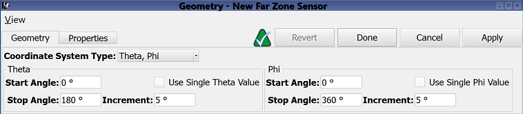
Under the geometry tab, users can define where to collect far zone data by choosing a Coordinate System Type: Theta/Phi, Alpha/Epsilon, or Elevation/Azimuth.
The selected coordinate system determines the available field values and settings below. By default, the theta, phi coordinate system's start and stop angles define a 3-D radiation pattern.
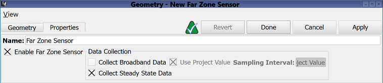
Under the properties tab, users can choose to collect either broadband or steady-state data.
The Collect Broadband Data option computes time-domain far-field results during timestepping. A fast Fourier transform (FFT) of the time-domain signal provides broadband results. The default Use Project Value setting determines the sampling interval according to project properties editor specifications, including the Use Automatic Time Domain Data Sampling Interval setting, frequency range of interest, and active waveforms. Deselecting the default setting allows users to manually enter a sampling interval.
Users should note that computation time increases with the number of specified angles, and this calculation is therefore recommended when far-zone results are desired at only a few points, as well as when far-zone time-domain fields are needed.
The Collect Steady State Data option computes steady-state tangential electric and magnetic fields on the far-zone box in a manner consistant with all steady-state data. As a post-processing step, the near- to far-field transform computes the far-field data.