The  Dielectric Breakdown Sensor detects possible damages caused by an electrostatic discharge in a geometric location of interest.
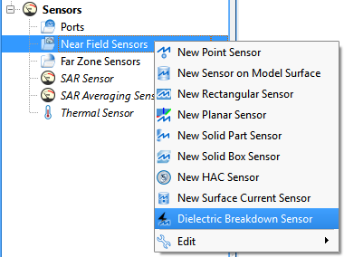
Users can create a dielectric breakdown sensor by right-clicking on Near Field Sensors in the Project Tree, then selecting Dielectric Breakdown Sensor. The editor across the top of the Geometry window consists of two tabs: Properties and Bounding Box.
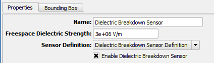
Under the Properties tab, users can enter a Name and change the Freespace Dielectric Strength. A finite dielectric strength must be associated with each cell edge in the simulation space where XF should monitor for damage. Users can define the properties of the free space surrounding the parts by setting this default value.
Users can specify the associated Sensor Definition by choosing from the current project's existing sensor definitions listed in the drop-down menu. The sensor definition specifies when cell edge data is checked for breakdown and saved to disk for visualization.
The checked Enable Dielectric Breakdown Sensor option includes the sensor's request in a simulation. When the option is unchecked, data is not collected during the simulation, but the sensor remains in the project for later use.
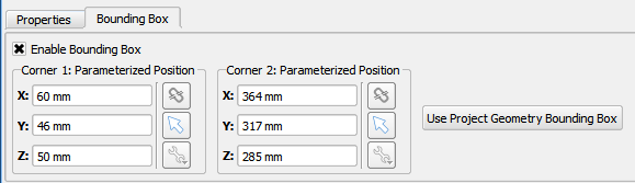
Under the Bounding Box tab, users can check the Enable Bounding Box option to collect data from a volume of interest defined by the entered coordinates. This reduces computational expense by ignoring the area outside the defined boundary. Clicking the Use Project Geometry Bounding Box button defines a bounding box that includes all geometry.
By default, the unchecked Enable Bounding Box option causes the sensor to collect data from the entire simulation space.