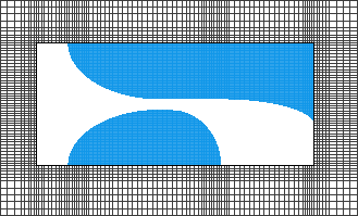
This example demonstrates how to discretize a vivaldi antenna by utilizing the gridding workflow.
Complete the following prerequisite steps during project setup:
- Set the project's frequency range of interest.
- Import the CAD geometry.
- Define materials and assign them to each part.
- Apply a modal waveguide excitation to the stripline.
- Set the outer boundaries to absorbing.
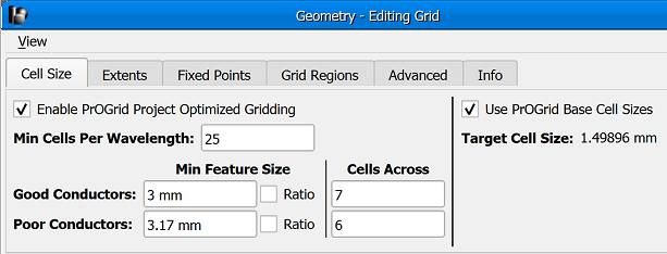
Next, apply the following grid settings:
- The main grid settings are adjusted according to the width of the stripline and the thickness of the substrate, as well as the desired cell size.
- Set the minimum cells per wavelength to 25.
- Set the minimum feature size for good conductors to 3 mm with 7 cells across.
- Set the minimum feature size for poor conductors to 3.17 mm with 6 cells across.
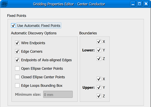
- Automatic fixed points are extracted from both the center conductor and substrate.
Finally, apply the following mesh settings:
- Apply XACT Accurate Cell Technology® to the three curved conductors.
- Apply Dielectric volume averaging to the substrate.
This video includes the following topics:
- [0:46] Main grid settings.
- [3:18] Grid visualization tools.
- [4:58] Automatic fixed points for center conductor and substrate.
- [6:41] XACT and dielectric volume averaging mesh settings.
- [8:10] Parts list.
Prerequisites
Prior to beginning the gridding steps, the frequency range of interest in the project properties editor is set to the antenna's operating range of 2 GHz to 8 GHz. The antenna includes three conductors—similar conductors on the top and bottom flared toward the outer edge and one in the center flared in the opposite direction. The center conductor includes a 3 mm wide stripline and is embedded in a 3.17 mm thick substrate.
The substrate's dielectric material has a relative permittivity of 2.33 that produces a shorter wavelength than is found in free space, and the three conductors are assigned a copper material definition that generates strong field gradients around their edges. A modal waveguide source is applied at the stripline, and absorbing outer boundaries on all six sides allow for antenna analysis in free space.
Standard Main Grid Properties
Check Grid
A visual inspection of the grid verifies that PrOGrid is applied and incorporating pertinent project settings:
- The minimum cells per wavelength in free space and the dielectric are based on the project's frequency range of interest.
- Smaller cells appear around the edges of the good conductors where field gradients are strongest.
- The number of cells across the stripline and substrate each meet their specified minimum value.
Viewing the geometry along each of the three principle axes shows grid misalignment with both the center conductor and substrate. This must be corrected by adjusting the gridding properties of individual parts.
The grid visualization process continues until no further adjustments are necessary.


