December 12, 2017: The content below helps navigate the new features in this release. A full list of updates is available in the Reference Manual's Appendix.
Customers using graphics processing unit (GPU) acceleration must upgrade their video drivers in order to support CUDA 8.0. CUDA 8.0 drops support for compute capability 1.x, which means that cards C1080 and older are not supported by XF 7.7.0 and subsequent versions. Support continues for C20x0 and higher, but users should note that NVIDIA and XF will drop support for these within a couple years.
XF 7.7.0 upgrades FLEXlm licensing libraries to version v11.14.1-TRL from v11.10.1. Customers using a floating license must update their floating license server. Customers using a green 9-key USB dongle must upgrade their USB driver.
Circuit Co-Simulation
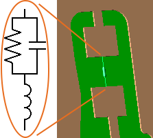
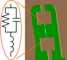
XF's circuit co-simulation capability is a time-domain circuit simulation that occurs in conjunction with the finite-difference time-domain (FDTD) simulation. The netlist component allows users to simulate manufacturer components—for example, capacitors from Murata—based on their measured data. By importing a text file, users can define passive SPICE3 models as just one component within the FDTD simulation.
The netlist component capability may also be used to to define a matching circuit within a feed. After importing a netlist file, users can create a netlist component definition that can then be assigned as a matching circuit in the feed editor. This single circuit component definition eliminates the need to create a matching circuit for each feed.
Nodal Waveguide Interface
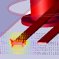
This release introduces nodal waveguide interface capabilities for computing single-ended S-parameters for transmission lines, including differential pairs and multi-pin connectors. The interface allows users to select transmission line pins and apply a user-defined reference impedance, creating an impedance mismatch at the source. The mismatch is exhibited in the renormalized S-parameters that are computed during simulation. A nodal excitation can also be applied to a set of pins without collecting S-parameters.
The name of the existing waveguide capability from previous XF versions has been changed to modal waveguide.
Circular and Elliptical Plane Waves
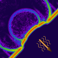
XF's plane wave capabilities now include circular and elliptical polarization, which take the following forms:
Circular: $(E_x + jE_y)e^{j\omega z}$
Elliptical: $(E_x + E_ye^{j\psi})e^{j\omega z}$
Both polarizations allow users to define electric field components, and the elliptical polarization allows users to define phase offset. These plane wave excitations compute scattering behavior and radar cross section.
Optimization Functions
Optimization functions added to the script API are accessible to users and allow them to optimize any result type, including S-parameters, gain, and efficiency. Users can perform multi-variable optimization based on the parameters in XF's parameters list.
N Pole Debye-Drude Material
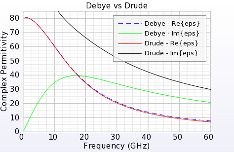
XF's electric Debye-Drude material definition has been extended to support n poles. This capability provides more flexibility when fitting an XF material to a measured material.
Meshing Order Rules
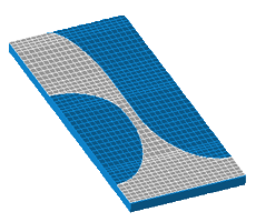
XF now adheres to three rules for determining meshing order:
- Select part with higher meshing priority.
- If priorities are equal, then select part with higher electric conductivity.
- If materials are equal, then select part that is closer to the top of the project tree.
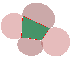
XF looks at the material properties and sets the meshing order based on a material's conductivity. This standard for distinguishing two overlapping parts ensures they are correctly applied to the mesh, and also allows users to make any necessary adjustments.
When users open a project saved in an earlier version of XF, the previous meshing order rules are disregarded. A message appears stating that the new rules have been applied, so users should recheck the mesh.
Remove Holes
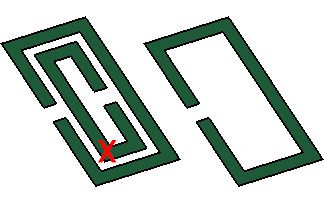
The remove holes modeling capability modifies a sheet body, allowing XF users who perform a PCB wrap operation during import to remove holes in the target part.
User-Defined Waveform
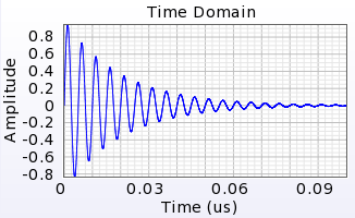
This release adds usability improvements to XF's user-defined waveform, allowing users to enter equations directly. The built-in functions include sin(t), exp(t), and pow(x,y), as well as constants, such as PI, c, and E, that can be used when defining the waveform's equation.
The following exponentially decaying sinusoidal waveform example utilizes both:
amplitude( t ) = E ^ ( -5e7 * t ) * sin( 2 * PI * 2e8 * t )
The file format for imported waveforms has been simplified so that it is based on physical time rather than timesteps. Each line of the file contains a time in seconds, one or more whitespace characters, and the waveform amplitude at that time.
Facet Properties
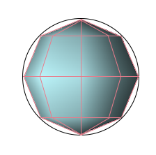
XF's faceting options are accessible to users, allowing them to increase the resolution from the default behavior. Adjusting a part's facet quality helps smooth the appearance of curved surfaces for a more accurate representation, particularly when XACT is enabled.
Multiple PCB Crop Sections
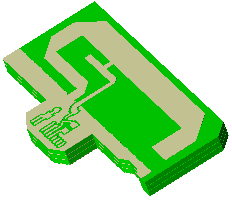
The PCB import window allows users to specify and import multiple crop regions at once rather than importing each crop section individually.
The following options can be applied while working within the PCB import window:
- Freehand line mode is the default behavior. Left-click the mouse to draw the polygon, right-click to close the current polygon and begin drawing another one, or use the following hotkey options:
- v: draws vertical, y-axis aligned lines.
- h: draws horizontal, x-axis aligned lines.
- o: draws lines orthogonal to the previous line once at least one line segment has been drawn.
- r: switches to rectangle mode, which is only available if a polygon has not been started.
- Ctrl+ click: deletes a polygon.
- Rectangle mode is the secondary method. Left-click once to start the rectangle and again to finish it, or use the following hotkey options:
- Ctrl+ click: deletes a polygon.
- f: returns to freehand mode.
Check Model
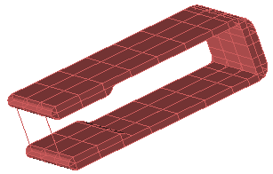
XF's new check model capability is a diagnostic tool that exposes issues stemming from an inconsistent model. After importing a 3-D CAD model, users can perform a check to identify errors upon noticing a failed modeling operation or flawed mesh. The check model feature provides information that helps users determine the next step toward resolving geometry issues.
Additional Capabilities
There are over 70 usability, performance, scripting, and other updates in this version.
Here is a select list of modifications:
- Added pull arrow to thicken sheet.
- Updated the dispersive material calculator to handle n pole Debye-Drude materials.
- Added port names to header information in Touchstone files.
- Added a right-click menu option in the simulations window to delete output files for simulations with a completed or killed status.
- Added support for multiple selection in the simulations window.
- Added dielectric volume averaging support for Debye-Drude materials.
- Added ability for electric Debye-Drude materials to touch, intersect, or colocate with a waveguide interface.
- Added PCB import support for multiple polygons and additional tools for specifying the design region(s) being imported.
- Added ability to scale facet-based parts.
- Added click-to-select capability to any object rendered in the geometry window, including circuit components, waveguides, and sensors.
- Improved visualization performance of large planar, solid volume, and surface sensors by 2.5-3x.
- Increased the solver's mesh file writing performance up to 40x in certain cases.
- Included additional information that shows number edges when performing several modeling operations, such as blend and chamfer.
- Improved handling of boolean modeling operations for success in many cases that previously failed with errors.
- Improved accuracy of plane wave simulations by correcting for anisotropic numerical dispersion.
- Improved TEM waveguide model shapes for increased likelyhood of the frequency domain solver finding proper single-ended modes when it finds degenerate TEM modes.
- Changed the default selection tool in the geometry window to the zoom-to-selection tool. Users can zoom to extents by either clearing the selection or using Shift+.
- Included port names in the header section of an exported Touchstone file.
- Updated application preferences to include saving and restoring the visibility state of project tree branches.
- Improved the selection tool in graphs by removing default behavior of zoom-to-box.
- Improved the rectangle select tool in the geometry window with behavior similar to the normal selection tool.
- Added ability to select multiple plots in a graph for editing and deleting.
- Added deselect all button for S-parameters in the create simulation window.
- Expanded list of available bands in the circuit element optimizer (CEO).
- Removed tip-of-the-day on startup.
- Added a copy all option to the right-click menu of most application text for quick copying to the clipboard.
- Added command-line parameter to XFsolver that accepts the path to a simulation or run directory, eliminating the need to change the current working directory before running XFsolver.
- Resolved crash when performing a wrap sheet modeling operation.
- Updated the included cuda_memtest program to support more than eight GPUs.
- [Scripting API] Added method App.getObjectSelection(), which enables scripts to access the current selection in the application.
- [Scripting API] Added methods on Simulation: getRunError(), getRunWarning(), getSimulationCreationReport(), deleteOutput(), and setQueued()
- [Scripting API] Added missing methods to set and get edges to OffsetSheetEdges
- [Scripting API] Added CopyFaces.detach property.
- [Scripting API] Added documentation for RObject.isValid() and RObject.getReasonWhyInvalid()
- [Scripting API] Added SimpleDialog.setLayoutMargin() and SimpleGroupBox.setLayoutMargin() that tightens up layouts for user-interface elements requiring many elements.
- [Scripting API] Added missing result types AttenuationConstant and PhaseConstant to ResultQuery
